Since 1996, if you’re in the United States and own a car or light truck, it’s mandated to be OBD-II compliant. In Europe, the regulations are a bit more nuanced. This standardization ensures that your vehicle has an onboard diagnostics system ready to communicate important information about its health and performance. But, not all OBD-II systems communicate in the same way. They use different protocols, and understanding which one your car uses is key to effectively using diagnostic tools.
OBD-II compliant vehicles can employ one of five communication protocols. These are J1850 PWM, J1850 VPW, ISO9141-2, ISO14230-4 (also known as Keyword Protocol 2000), and the more modern ISO15765-4/SAE J2480, which is a type of CAN (Controller Area Network). It’s interesting to note that in the US, manufacturers weren’t permitted to use CAN until the 2003 model year. However, from 2008 onwards, CAN became the standard protocol for all vehicles.
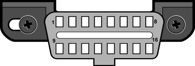
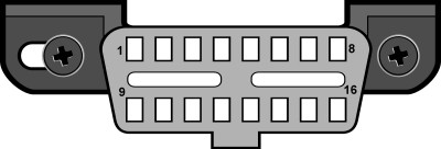
To connect to your car’s OBD-II system, you’ll need to locate the Diagnostic Link Connector (DLC). SAE J1962 defines two types of DLCs: Type A and Type B. The primary difference between them lies in the shape of their alignment tab, as you can see in the images below.
According to SAE J1962, the Type A DLC is typically found within the passenger or driver’s compartment. Specifically, it should be located in the area stretching from the driver’s side of the instrument panel to about 300 mm (or roughly 1 foot) beyond the vehicle’s centerline. It’s designed to be attached to the instrument panel for easy access from the driver’s seat. The area between the steering column and the vehicle’s centerline is the most common and preferred spot.
Type B DLCs have a broader potential location range. They are also placed in the passenger or driver’s compartment, starting from the driver’s end of the instrument panel, including the outer side, and extending to an imaginary line about 750 mm (or 2.5 feet) beyond the vehicle centerline. Like Type A, it’s attached to the instrument panel but must be easily accessible not only from the driver’s seat but also from the co-driver’s seat or even from outside the vehicle. The mounting of the vehicle connector is designed to make connecting and disconnecting easy.
While connector types are helpful to know, the real key to figuring out your OBD-II protocol lies in examining the pinout of your DLC. The pinout configuration will tell you which protocol your vehicle employs.
The table below simplifies protocol identification based on which pins are populated in your OBD-II connector.
| Pin 2 | Pin 6 | Pin 7 | Pin 10 | Pin 14 | Pin 15 | Standard |
|---|---|---|---|---|---|---|
| must have | – | – | must have | – | – | J1850 PWM |
| must have | – | – | – | – | – | J1850 VPW |
| – | – | must have | – | – | may have* | ISO9141/14230 |
| – | must have | – | – | must have | – | ISO15765 (CAN) |
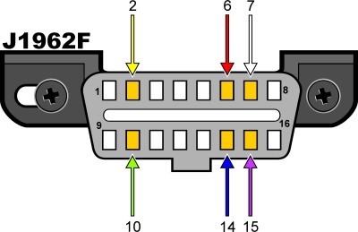
*Note: Pin 15, sometimes referred to as the “L-line,” might be optional in newer vehicles utilizing the ISO9141-2 or ISO14230-4 protocols.
Regardless of the protocol, certain pins are consistently required. Pins 4 (Chassis Ground), 5 (Signal Ground), and 16 (Battery Positive) should always be present in the connector.
To make it even easier, here’s a summary of the essential pin combinations for each protocol:
| Protocol | Required Pins |
|---|---|
| PWM | Pins 2, 4, 5, 10, and 16 |
| VPW | Pins 2, 4, 5, and 16, but not 10 |
| ISO | Pins 4, 5, 7, and 16. Pin 15 may or may not be present. |
| CAN | Pins 4, 5, 6, 14, and 16 |
By checking the pins in your vehicle’s OBD-II connector against these tables, you can confidently determine “What Obd2 Protocol Is My Car” uses. This knowledge is crucial for selecting the right diagnostic tools and ensuring proper communication with your vehicle’s computer system. You may also find online resources, like the OBDII Generic Communication Protocols by Manufacturer list, helpful for further investigation.