Understanding what data your car’s OBD2 system provides is crucial for modern vehicle diagnostics, maintenance, and performance monitoring. This guide offers an in-depth look at OBD2 data, going beyond a basic introduction to explore the specifics of what information you can access and how it’s used.
You can also watch our OBD2 intro video above – or get the PDF
Decoding OBD2: Unveiling Your Vehicle’s Data
OBD2, or On-Board Diagnostics II, is essentially your car’s health monitoring system. It’s a standardized protocol implemented in most modern vehicles that allows you to access a wealth of diagnostic information and real-time data. But what data does OBD2 actually provide?
Think of the malfunction indicator light (check engine light) on your dashboard. When this illuminates, it’s a signal that your car has detected an issue. An automotive technician uses an OBD2 scanner to connect to your vehicle’s OBD2 system via the OBD2 16 pin connector, typically located under the dashboard.
The OBD2 scanner sends requests, and the car responds with data. This data can range from simple parameters like speed and engine RPM to more complex information like emission levels and diagnostic trouble codes (DTCs). This capability allows for faster and more accurate troubleshooting and vehicle health assessments.
Understanding the malfunction indicator light (MIL) is the first step in recognizing the value of OBD2 data for vehicle diagnostics.
OBD2 Data Availability: Is Your Car Compatible?
The good news is that most non-electric cars manufactured in recent decades are OBD2 compliant. While older vehicles might have a 16-pin connector that resembles an OBD2 port, it doesn’t guarantee OBD2 support. Compliance is largely determined by the vehicle’s origin and year of manufacture.
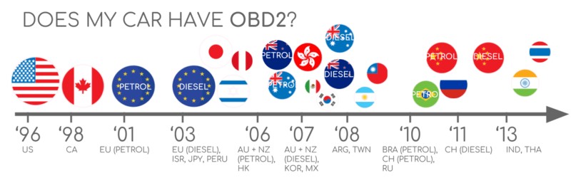
Here’s a general guideline for OBD2 compliance based on the region where the car was initially sold:
A visual guide to determine OBD2 compliance based on vehicle origin and manufacturing timeline, crucial for understanding data accessibility.
A Brief History of OBD2 and Its Data Focus
OBD2’s origins are rooted in California, driven by the California Air Resources Board (CARB). Starting in 1991, CARB mandated OBD systems in new cars for emission control. The Society of Automotive Engineers (SAE) further developed the standard, leading to standardized DTCs and the OBD connector (SAE J1962).
The OBD2 standard adoption unfolded gradually:
- 1996: OBD2 became mandatory in the USA for cars and light trucks.
- 2001: Required in the EU for gasoline cars.
- 2003: Extended to diesel cars in the EU (EOBD – European On-Board Diagnostics).
- 2005: Mandated in the US for medium-duty vehicles.
- 2008: US vehicles were required to use ISO 15765-4 (CAN) as the OBD2 communication foundation.
- 2010: OBD2 became mandatory for US heavy-duty vehicles.
Initially focused on emissions, OBD2’s data provision has expanded significantly, becoming a valuable source of broader vehicle operational data.
The historical evolution of OBD2, highlighting its initial focus on emissions and subsequent expansion to broader vehicle data.
A timeline visualization of OBD2 history, showing the progressive adoption and mandates across different regions and vehicle types.
Looking towards the future of OBD, including OBD3 and remote diagnostics, suggesting future trends in data accessibility and utilization.
The Future of OBD2 Data: Trends and Challenges
While OBD2 remains relevant, the automotive landscape is evolving. Electric vehicles (EVs), for example, are not obligated to support OBD2 in its traditional form. Most EVs utilize OEM-specific UDS communication, making standardized OBD2 data access less common. However, reverse engineering efforts are making inroads into accessing EV data, as seen in case studies for brands like Tesla, Hyundai/Kia, Nissan, and VW/Skoda.
Alternatives like WWH-OBD (World Wide Harmonized OBD) and OBDonUDS (OBD on UDS) are emerging to address limitations in data richness and communication protocols. These aim to enhance OBD communication using the UDS protocol as a foundation. Further details are available in introductions to UDS protocol.
The concept of OBD3 is also being discussed, envisioning telematics integration for continuous, remote emission monitoring. This would involve transmitting vehicle identification numbers (VIN) and DTCs wirelessly for centralized checks. Devices like CANedge2 and CANedge3 already facilitate data transfer via WiFi/cellular networks. However, data privacy concerns present political challenges for widespread OBD3 implementation.
Interestingly, while OBD2 was designed for emission checks, its real-time data capabilities are now widely used by third-party services via OBD2 dongles and CAN loggers. However, some automotive manufacturers are seeking to restrict this third-party access, potentially centralizing data control for commercial purposes, citing security concerns like car hacking risks. This could significantly alter the landscape of OBD2-based services.
The challenge of data access in electric vehicles, representing a shift in OBD2 applicability and data availability.
Deep Dive: The ‘Ultimate CAN Guide’
Want to become a CAN bus expert?
Our 160+ page PDF ‘Ultimate Guide’ provides 12 simple introductions.
Download now
OBD2 Standards: Defining Data Parameters
OBD2 operates as a higher-layer protocol built on communication methods like CAN. It’s comparable to other CAN-based protocols like J1939, CANopen, and NMEA 2000.
OBD2 standards define several key aspects, including the OBD2 connector, lower-layer protocols, and importantly, OBD2 parameter IDs (PIDs), which dictate the specific data points accessible. These standards are structured using a 7-layer OSI model, with SAE and ISO standards overlapping, reflecting US and EU standardization efforts. For example, SAE J1979 and ISO 15031-5 are functionally equivalent for diagnostic services, as are SAE J1962 and ISO 15031-3 for the OBD connector.
The OSI model representation of OBD2 and CAN bus, illustrating the layered structure of communication protocols and standards.
A detailed pinout diagram of a Type A OBD2 connector, highlighting the physical interface for data access.
The OBD2 Connector: Your Data Access Point
The 16-pin OBD2 connector, standardized under SAE J1962 / ISO 15031-3, is the physical interface for accessing OBD2 data. This Data Link Connector (DLC) is typically located near the steering wheel, though its exact location can vary.
Key features of the OBD2 connector include:
- Location: Usually near the steering wheel, but sometimes hidden.
- Pin 16: Provides battery power, even when the ignition is off.
- Pinout: Varies based on communication protocol.
- CAN bus: Pins 6 (CAN-H) and 14 (CAN-L) are commonly used for CAN bus communication.
OBD2 Connector Types: A vs. B
Two main OBD2 connector types exist: Type A and Type B. Type A is standard in cars, while Type B is more common in medium and heavy-duty vehicles. While pinouts are similar, they differ in power supply (12V for Type A, 24V for Type B) and often baud rates (500K for cars, 250K or 500K for heavy-duty vehicles).
Type B connectors have a distinguishing interrupted groove, making Type B adapters compatible with both sockets, but Type A adapters incompatible with Type B sockets.
Comparison of OBD2 Connector Type A and Type B, emphasizing differences in power supply and application.
A visual representation of the relationship between OBD2 and CAN bus, highlighting ISO 15765 as the standard for OBD2 over CAN.
OBD2 and CAN Bus: The Data Communication Network
Since 2008, CAN bus (ISO 15765) has been the mandatory lower-layer protocol for OBD2 in US vehicles. ISO 15765-4, or Diagnostics over CAN (DoCAN), standardizes the CAN interface for diagnostic equipment, focusing on physical, data link, and network layers.
Key specifications for OBD2 over CAN include:
- Bit-rate: 250K or 500K.
- CAN IDs: 11-bit or 29-bit.
- Specific CAN IDs: Designated for OBD requests and responses.
- Data length: 8 bytes per diagnostic CAN frame.
- Adapter cable length: Maximum 5 meters.
OBD2 CAN Identifiers: Addressing Data Requests
OBD2 communication uses request/response message pairs. In most cars, 11-bit CAN IDs are used. Functional addressing uses ID 0x7DF to query all OBD2-compatible ECUs. Physical addressing uses IDs 0x7E0-0x7E7 for specific ECU requests (less common).
ECU responses typically use 11-bit IDs 0x7E8-0x7EF, with 0x7E8 (Engine Control Module – ECM) being the most common and 0x7E9 (Transmission Control Module – TCM) also frequently used.
Some vehicles, particularly larger vehicles, may use extended 29-bit CAN identifiers for OBD2. Functional addressing here uses 0x18DB33F1, with responses ranging from 0x18DAF100 to 0x18DAF1FF (commonly 0x18DAF110 and 0x18DAF11E). This response ID is also sometimes referred to by its ‘J1939 PGN’ designation, PGN 0xDA00 (55808), marked for ISO 15765-2 in the J1939-71 standard.
Illustration of OBD2 request and response frames, highlighting the flow of data parameters and PIDs.
Distinction between OBD2 data and proprietary OEM-specific CAN bus data, clarifying the scope of standardized vs. manufacturer-specific vehicle information.
OBD2 vs. Proprietary CAN Protocols: Data Scope
It’s crucial to understand that OBD2 is an additional protocol layered on top of a vehicle’s core communication network. Vehicle ECUs primarily operate using proprietary CAN protocols defined by the OEM, which are specific to the vehicle brand, model, and year. These OEM protocols handle essential vehicle functions, and this data is generally inaccessible without reverse engineering.
Connecting a CAN bus data logger to the OBD2 port might capture OEM-specific CAN data, typically broadcast at high rates. However, modern vehicles often employ a ‘gateway’ that restricts OBD2 port access to OBD2 communication only, blocking access to the underlying OEM CAN data.
OBD2 is best viewed as a parallel, standardized data access layer, separate from the OEM-specific protocols that govern core vehicle operations.
Bit-rate and ID Validation: Ensuring Data Integrity
OBD2 can operate at two bit-rates (250K, 500K) and with two CAN ID lengths (11-bit, 29-bit), resulting in four possible combinations. Modern cars commonly use 500K and 11-bit IDs, but diagnostic tools should systematically validate these settings.
ISO 15765-4 outlines a validation sequence, leveraging a mandatory OBD2 request to test compatibility and using CAN error frames to detect incorrect bit-rate settings. Newer versions of ISO 15765-4 also account for OBDonUDS communication in addition to OBDonEDS (OBD on Emission Diagnostic Service). Tools can test for OBDonUDS support by sending UDS requests with specific service and data identifier (DID) codes.
In practice, OBDonEDS (or OBD2, SAE OBD, EOBD, ISO OBD) is prevalent in most non-EV cars, while WWH-OBD is primarily used in EU trucks and buses.
A flowchart illustrating the process of OBD2 bit-rate and CAN ID validation, as per ISO 15765-4 standards.
Overview of the five lower-layer OBD2 protocols, including CAN (ISO 15765) and older protocols like KWP2000 and SAE J1850.
Five Lower-Layer OBD2 Protocols: Historical Context
While CAN (ISO 15765) is dominant today, older vehicles may utilize other lower-layer protocols for OBD2. Understanding these is helpful when working with pre-2008 cars. Pinouts can often indicate the protocol in use.
- ISO 15765 (CAN bus): Mandatory in US cars since 2008 and widely used today.
- ISO14230-4 (KWP2000): Common in 2003+ Asian cars.
- ISO 9141-2: Used in EU, Chrysler, and Asian cars (2000-04).
- SAE J1850 (VPW): Primarily used in older GM vehicles.
- SAE J1850 (PWM): Primarily used in older Ford vehicles.
ISO-TP: Transporting OBD2 Data
OBD2 messages are transported over CAN using ISO-TP (ISO 15765-2), a transport protocol that allows for payloads exceeding the 8-byte CAN frame limit. This is essential for transmitting larger OBD2 data like VIN or DTCs. ISO-TP manages segmentation, flow control, and reassembly of these larger messages. More details can be found in introductions to UDS.
For smaller OBD2 data packets that fit within a single CAN frame, ISO-TP uses ‘Single Frame’ (SF) format. The first byte of data (PCI field) indicates the payload length, leaving 7 bytes for OBD2 communication.
Illustration of ISO-TP frame types used in OBD2 communication, including Single Frame, First Frame, Consecutive Frame, and Flow Control Frame.
The OBD2 Diagnostic Message: Anatomy of Data
A raw ‘Single Frame’ OBD2 CAN message contains an identifier, data length (PCI field), and data payload. The payload itself is structured into Mode, parameter ID (PID), and data bytes.
Breakdown of an OBD2 message structure, showing the arrangement of Mode, PID, and data bytes within a CAN frame.
OBD2 Request/Response Example: Vehicle Speed
Consider requesting ‘Vehicle Speed’ as an example. A tool sends a request with CAN ID 0x7DF, containing Mode 0x01 and PID 0x0D. The car responds with CAN ID 0x7E8, including the speed value in the 4th byte, say 0x32 (decimal 50). Using OBD2 PID documentation, 0x32 translates to 50 km/h.
Example of an OBD2 request and response sequence for vehicle speed, showing CAN IDs and data payload bytes.
Detailed example focusing on OBD2 PID 0x0D (Vehicle Speed), illustrating the request, response, and data interpretation.
Overview of the 10 OBD2 diagnostic services or modes, ranging from real-time data to DTC management.
The 10 OBD2 Services (Modes): Data Categories
OBD2 defines 10 diagnostic services, also called modes. Mode 0x01 provides real-time data, while others handle DTCs, freeze frame data, and more. Vehicles aren’t required to support all modes and may include OEM-specific modes beyond the standard 10.
In OBD2 messages, the mode is the second byte. In requests, the mode is directly included (e.g., 0x01). In responses, 0x40 is added to the mode value (e.g., 0x41 for a response to mode 0x01).
OBD2 Parameter IDs (PIDs): Specific Data Points
Each OBD2 mode contains Parameter IDs (PIDs). Mode 0x01, for example, includes approximately 200 standardized PIDs for real-time data like speed, RPM, and fuel level. However, vehicles typically support only a subset of these PIDs.
A crucial PID is mode 0x01 PID 0x00. If an emissions-related ECU supports OBD2, it must support this PID. Responding to PID 0x00, the ECU indicates support for PIDs 0x01-0x20. This makes PID 0x00 a fundamental OBD2 compatibility test. PIDs 0x20, 0x40, 0x60, etc., similarly indicate support for subsequent PID ranges within mode 0x01.
(Repeated image for context, as it is relevant to the discussion of PIDs)
Screenshot of an OBD2 PID overview tool, demonstrating the interface for exploring and understanding OBD2 service 01 data parameters.
OBD2 PID Overview Tool: Data Decoding Aid
SAE J1979 and ISO 15031-5 appendices detail scaling information for standard OBD2 PIDs, enabling data conversion to physical values. Our OBD2 PID overview tool helps construct request frames and dynamically decode responses, simplifying data interpretation.
OBD2 PID overview tool
Logging and Decoding OBD2 Data: Practical Steps
Here’s a practical guide to logging OBD2 data using a CANedge CAN bus data logger. The CANedge allows custom CAN frame transmission for tasks like OBD2 logging and connects easily via an OBD2-DB9 adapter cable.
Diagram illustrating OBD2 data logging setup with a data logger requesting PIDs and receiving responses.
Reviewing supported PIDs using software like asammdf, crucial for identifying available data parameters.
Step #1: Bit-rate, ID, and Supported PID Testing
ISO 15765-4 details how to determine vehicle-specific bit-rate and IDs. Using CANedge:
- Test at 500K bit-rate; if successful, use it (else try 250K).
- Use the confirmed bit-rate for further communication.
- Send ‘Supported PIDs’ requests to identify available PIDs.
- Response IDs indicate 11-bit or 29-bit IDs.
- Response data reveals supported PIDs.
Pre-configured setups are available for these tests. Most 2008+ non-EV cars support 40-80 PIDs using 500K, 11-bit CAN IDs, and OBDonEDS.
Multiple responses to a single request (using 0x7DF) are common as it polls all ECUs. The ECM ECU (0x7E8) often supports all PIDs other ECUs support, allowing reduced bus load by targeting ECM directly using ‘Physical Addressing’ CAN ID 0x7E0 for subsequent requests.
Step #2: Configuring OBD2 PID Requests
Once you know supported PIDs, configure your transmit list. Consider:
- CAN IDs: Use ‘Physical Addressing’ (e.g., 0x7E0) to target specific ECUs and reduce response redundancy.
- Spacing: Add 300-500 ms delay between requests to avoid overwhelming ECUs.
- Battery drain: Use triggers to stop transmissions when the vehicle is inactive.
- Filters: Filter to record only OBD2 responses if OEM-specific CAN data is also present.
With these settings, your logger is ready to capture raw OBD2 data.
Example of a CANedge OBD2 PID request transmit list configuration, showing PID requests and CAN IDs.
Visual plot of decoded OBD2 data in asammdf, demonstrating data visualization and analysis using DBC files.
Step #3: DBC Decoding of Raw OBD2 Data
To analyze and visualize logged data, decode raw OBD2 data into physical values. ISO 15031-5/SAE J1979 and resources like Wikipedia provide decoding information. A free OBD2 DBC file simplifies DBC decoding in CAN bus software.
OBD2 decoding is more complex than standard CAN signals because multiple PIDs share the same CAN ID (e.g., 0x7E8). Decoding requires considering CAN ID, OBD2 mode, and PID – a form of ‘extended multiplexing’ manageable with DBC files.
CANedge: Your OBD2 Data Logging Solution
The CANedge simplifies OBD2 data recording to SD cards (8-32 GB). Connect it to a vehicle to log data and use free software/APIs and our OBD2 DBC for decoding.
OBD2 logger intro CANedge
OBD2 Multi-Frame Examples: Handling Larger Data
OBD2 uses ISO-TP for all communication, including multi-frame messages for data exceeding 8 bytes. Multi-frame communication involves flow control frames. CANedge configurations can include static flow control frames sent shortly after requests. Software tools like CANedge MF4 decoders are needed for processing multi-frame OBD2 responses.
Example of a multi-frame request message for Vehicle Identification Number (VIN) retrieval using OBD2.
Example 1: Vehicle Identification Number (VIN) Retrieval
VIN retrieval (mode 0x09, PID 0x02) is common for telematics and diagnostics.
The tool sends a Single Frame request. The vehicle responds with a First Frame indicating the total data length, mode, and PID, followed by data bytes including the VIN (translated from HEX to ASCII).
Example 2: Multi-PID Request (6x)
OBD2 allows requesting up to 6 mode 0x01 PIDs in one request for efficient data collection. However, response encoding is request-specific, making generic DBC files less useful. This method is not generally recommended due to complexity.
The multi-frame response contains data for requested PIDs, often in the requested order. Decoding requires request-specific logic and is difficult to generalize across vehicles or manage at scale, especially with multiple multi-PID requests.
Example 3: Diagnostic Trouble Codes (DTCs)
Mode 0x03 (‘Show stored Diagnostic Trouble Codes’) retrieves emissions-related DTCs. No PID is in the request. ECUs respond with the number of DTCs and 2-byte DTC codes. Multi-frame responses are necessary for more than 2 DTCs.
DTCs are 2-byte values, categorized and coded as per ISO 15031-5/ISO 15031-6. Decoded DTCs can be looked up using OBD2 DTC lookup tools like repairpal.com.
DTC decoding example, showing the structure of a 2-byte DTC code and its interpretation.
The example shows a request to an ECU with 6 stored DTCs, resulting in a multi-frame response containing the DTC codes.
OBD2 Data Logging: Real-World Applications
OBD2 data from cars and light trucks has numerous applications:
Car Data Logging
OBD2 data logging can help reduce fuel costs, improve driving habits, test prototype components, and inform insurance models.
obd2 logger
Real-time Car Diagnostics
OBD2 interfaces enable real-time streaming of vehicle data for immediate diagnostics and issue identification.
obd2 streaming
Predictive Maintenance
IoT-connected OBD2 loggers allow for remote vehicle monitoring to predict and prevent breakdowns.
predictive maintenance
Vehicle Black Box
OBD2 loggers serve as ‘black boxes’ for vehicles, providing data for accident analysis, dispute resolution, and detailed diagnostics.
can bus blackbox
Have an OBD2 data logging application in mind? Contact us for expert consultation!
Contact us
Explore our guides section for more introductions or download the ‘Ultimate Guide’ PDF.
Ready to log or stream OBD2 data?
Get your OBD2 data logger today!
Buy now Contact us
Further Reading
OBD2 DATA LOGGER: EASILY LOG & CONVERT OBD2 DATA
CANEDGE2 – PRO CAN IoT LOGGER
[