Ever wondered what’s going on under the hood of your car beyond just driving it? Modern vehicles are complex machines packed with sensors and computers, constantly monitoring and adjusting performance. OBD2, or On-Board Diagnostics II, is your key to accessing this wealth of information. But what can you actually do with OBD2?
This guide will provide you with a comprehensive understanding of OBD2, far beyond a simple introduction. We’ll delve into the practical applications, from diagnosing that pesky check engine light to enhancing your car’s performance and even exploring the future of automotive data. Whether you’re a seasoned mechanic or a curious car owner, understanding OBD2 opens up a world of possibilities.
Understanding OBD2 and the Malfunction Indicator Light (MIL), commonly known as the check engine light.
Demystifying OBD2: Your Car’s Diagnostic System
OBD2 is essentially your car’s built-in health monitoring system. It’s a standardized protocol that allows you to communicate with your vehicle’s computer, retrieve diagnostic trouble codes (DTCs), and access real-time data about its operation. Think of it as a universal translator that lets you understand what your car is trying to tell you.
You’ve likely encountered OBD2 indirectly if you’ve ever seen the “check engine light” illuminate on your dashboard. This light, officially known as the Malfunction Indicator Light (MIL), is a signal from your car’s OBD2 system indicating that it has detected an issue. When this light comes on, your car has stored a DTC, a code that pinpoints the area of the problem.
Mechanics rely heavily on OBD2 scanners to diagnose car problems efficiently. By connecting an OBD2 scanner to the standard 16-pin OBD2 connector, usually located under the dashboard near the steering wheel, they can send requests to the car’s computer and receive responses containing valuable diagnostic information. This data can include everything from engine speed and coolant temperature to fuel system status and, crucially, those Diagnostic Trouble Codes that help pinpoint malfunctions. OBD2 dramatically speeds up the diagnostic process, saving time and money on car repairs.
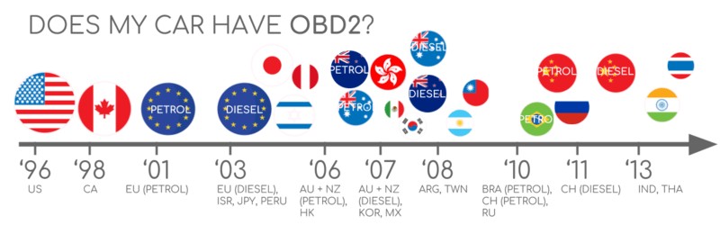
Is My Car OBD2 Compliant? Chances Are, Yes!
The good news is that if you own a relatively recent car, it almost certainly supports OBD2. For gasoline cars in the USA, OBD2 became mandatory in 1996 for cars and light trucks. The rollout continued globally, becoming required in the EU for gasoline cars in 2001 and diesel cars in 2003 (EOBD). By 2008, CAN bus became the mandatory communication protocol for OBD2 in US vehicles.
To quickly check if your car is likely OBD2 compliant, consider these general guidelines based on where and when it was originally purchased:
A helpful chart to determine OBD2 compliance based on vehicle purchase location and year.
While most modern non-electric vehicles are OBD2 compliant, and many use the CAN bus communication protocol, older cars with a 16-pin connector might not fully support OBD2. If you’re unsure, consulting your car’s owner’s manual or contacting the manufacturer is always recommended.
A Brief History of OBD2: From Emissions to Everyday Diagnostics
The story of OBD2 begins in California, driven by the need to control vehicle emissions. The California Air Resources Board (CARB) mandated OBD in all new cars from 1991 onwards for emissions monitoring. This initial OBD system laid the groundwork for the standardized OBD2 we know today.
The Society of Automotive Engineers (SAE) played a crucial role in standardizing OBD2, defining Diagnostic Trouble Codes and the universal OBD connector (SAE J1962). This standardization was a game-changer, allowing for consistent diagnostics across different manufacturers.
The OBD2 standard progressively became mandatory across different vehicle types and regions:
- 1996: OBD2 mandated in the USA for cars and light trucks.
- 2001: Required in the EU for gasoline vehicles.
- 2003: Extended to diesel vehicles in the EU (EOBD).
- 2005: OBD2 required in the US for medium-duty vehicles.
- 2008: US vehicles mandated to use ISO 15765-4 (CAN) as the foundation for OBD2 communication.
- 2010: OBD2 became mandatory for heavy-duty vehicles in the US.
Visualizing the historical progression of OBD2, starting with emission control and evolving into broader vehicle diagnostics.
A timeline summarizing key milestones in OBD2 history, from its inception to widespread adoption.
Looking ahead to OBD3 and the future trends of remote diagnostics, cloud connectivity, and IoT integration.
The Future of OBD2: Evolution and Challenges
OBD2 is not static; it’s evolving alongside the automotive industry. While originally focused on emissions control, its applications have expanded significantly. However, the rise of electric vehicles and increasing concerns about data access are shaping its future.
Electric vehicles (EVs), interestingly, are not mandated to support OBD2 in the same way as combustion engine vehicles. In practice, many modern EVs don’t support standard OBD2 requests. Instead, they often utilize manufacturer-specific UDS (Unified Diagnostic Services) protocols. This makes accessing data from EVs more challenging, often requiring reverse engineering to understand the communication protocols – as demonstrated in case studies for Tesla, Hyundai/Kia, Nissan, and VW/Skoda EVs.
To address the limitations of traditional OBD2 in terms of data richness and communication methods, newer protocols like WWH-OBD (World Wide Harmonized OBD) and OBDonUDS are emerging. These aim to enhance OBD communication by using UDS as a base, offering more streamlined and advanced diagnostic capabilities.
The connected car era is also pushing OBD towards OBD3, envisioning telematics integration. OBD3 proposes adding a transponder to vehicles, allowing for wireless transmission of Vehicle Identification Numbers (VIN) and DTCs to central servers for automated emission checks and diagnostics. While this offers convenience and cost savings, it also raises privacy concerns related to data surveillance. Devices like the CANedge2 and CANedge3 already facilitate data transfer via Wi-Fi and cellular networks, paving the way for connected OBD applications.
However, the future of OBD2 access for third parties is uncertain. Automakers, particularly in Germany, are considering restricting OBD2 functionality during driving, centralizing data collection and control within the manufacturer’s ecosystem. This shift, argued as a security measure against car hacking, is also seen by some as a move to control automotive data and potentially disrupt the market for third-party OBD2 services.
Illustrating the trend of electric vehicles potentially limiting access to data through the traditional OBD2 connector.
Deep Dive: OBD2 Standards and Protocols
OBD2 operates as a “higher-layer protocol” built upon communication methods like CAN bus. Think of OBD2 as the language spoken, and CAN bus as the communication channel. This is similar to other CAN-based protocols such as J1939, CANopen, and NMEA 2000.
OBD2 standards comprehensively define various aspects, including the OBD2 connector, lower-layer communication protocols, and OBD2 Parameter IDs (PIDs). These standards can be categorized within the 7-layer OSI model for network communication. Notably, both SAE (US standards) and ISO (international standards) contribute to OBD2 specifications, often with technically equivalent standards like SAE J1979 and ISO 15031-5 for diagnostics, and SAE J1962 and ISO 15031-3 for the connector.
The OSI Model illustrating how OBD2 and CAN bus protocols interact across different layers of communication.
The OBD2 Connector: Your Physical Access Point [SAE J1962]
The 16-pin OBD2 connector, standardized by SAE J1962 and ISO 15031-3, is your physical interface to your car’s diagnostic system. This connector allows easy access to vehicle data.
A detailed pinout diagram of a Type A OBD2 connector, highlighting key pins and their functions.
Key features of the OBD2 connector include:
- Its location is typically near the steering wheel, though sometimes hidden under a panel.
- Pin 16 provides battery power, often even when the ignition is off.
- The pinout configuration depends on the communication protocol used.
- CAN bus, the most common lower-layer protocol, utilizes pins 6 (CAN-High) and 14 (CAN-Low).
OBD2 Connector Types: A vs. B
You might encounter Type A and Type B OBD2 connectors. Type A is standard in cars, while Type B is more common in medium and heavy-duty vehicles. While pinouts are similar, Type A provides 12V power, and Type B provides 24V. Baud rates can also differ, with cars typically using 500K and heavy-duty vehicles often using 250K (though 500K support is increasing).
Type B connectors have a distinguishing interrupted groove in the middle. Type B OBD2 adapter cables are compatible with both Type A and Type B sockets, while Type A cables only fit Type A sockets.
Comparison of OBD2 Connector Type A and Type B, noting differences in voltage and typical vehicle applications.
OBD2 and CAN Bus: The Communication Backbone [ISO 15765-4]
Since 2008, CAN bus (Controller Area Network) has been the mandatory lower-layer protocol for OBD2 in US cars, as per ISO 15765. ISO 15765-4, also known as Diagnostics over CAN (DoCAN), specifies how OBD2 operates over CAN. It applies restrictions to the CAN standard (ISO 11898), standardizing the interface for diagnostic equipment at the physical, data link, and network layers.
Key ISO 15765-4 specifications include:
- CAN bus bit-rate must be 250K or 500K.
- CAN IDs can be 11-bit or 29-bit.
- Specific CAN IDs are designated for OBD requests and responses.
- Diagnostic CAN frame data length is fixed at 8 bytes.
- OBD2 adapter cable length must not exceed 5 meters.
Visual representation of the relationship between OBD2 and CAN bus, highlighting the ISO 15765 standard.
OBD2 CAN Identifiers (11-bit, 29-bit)
OBD2 communication relies on request/response message exchanges. In most cars, 11-bit CAN IDs are used. The ‘Functional Addressing’ ID, 0x7DF, is used to query all OBD2-compatible Electronic Control Units (ECUs) for data on a requested parameter. ‘Physical Addressing’ requests to specific ECUs can be made using CAN IDs 0x7E0-0x7E7, though this is less common.
ECUs respond with 11-bit IDs in the range 0x7E8-0x7EF. The most frequent response ID is 0x7E8 (Engine Control Module – ECM), followed by 0x7E9 (Transmission Control Module – TCM).
Some vehicles, particularly vans and medium/heavy-duty vehicles, may use extended 29-bit CAN identifiers for OBD2 communication. The ‘Functional Addressing’ CAN ID in this case is 0x18DB33F1. Responses use CAN IDs ranging from 0x18DAF100 to 0x18DAF1FF (typically 18DAF110 and 18DAF11E). These 29-bit IDs are sometimes represented in the J1939 PGN format, specifically PGN 0xDA00 (55808), which is reserved for ISO 15765-2 in the J1939-71 standard.
Illustrating the request-response communication flow in OBD2, showing parameter IDs and data parameters.
OBD2 vs. Proprietary CAN Protocols
It’s crucial to understand that OBD2 is a separate protocol from the manufacturer-specific CAN protocols that ECUs use for their internal operations. OEMs implement their own proprietary CAN protocols, which are often specific to vehicle brand, model, and year. Unless you have OEM-specific documentation or can reverse engineer these protocols, interpreting this raw CAN data is typically not possible.
When you connect a CAN bus data logger to your OBD2 port, you might see this OEM-specific CAN data, often broadcast at high rates (1000-2000 frames/second). However, newer cars often have a ‘gateway’ that filters this data, allowing only OBD2 communication through the OBD2 connector.
Think of OBD2 as an “add-on” protocol that runs alongside the vehicle’s core OEM communication network.
Contrasting OBD2 data with proprietary OEM-specific CAN bus data, highlighting the distinct nature of each.
Bit-rate and ID Validation
OBD2 can use two bit-rates (250K, 500K) and two CAN ID lengths (11-bit, 29-bit), resulting in four possible combinations. Modern cars commonly use 500K and 11-bit IDs. Diagnostic tools should systematically validate these parameters.
ISO 15765-4 provides a validation sequence to determine the correct combination. This method relies on the requirement that OBD2-compliant vehicles must respond to a mandatory OBD2 request (specifically, Mode 0x01 PID 0x00) and leverages the fact that incorrect bit-rates cause CAN error frames.
Newer versions of ISO 15765-4 consider OBD communication via OBDonUDS as well as OBDonEDS. This article primarily focuses on OBD2/OBDonEDS (OBD on Emission Diagnostic Service, as per ISO 15031-5/SAE J1979) rather than WWH-OBD/OBDonUDS (OBD on Unified Diagnostic Service, as per ISO 14229, ISO 27145-3/SAE J1979-2). OBDonEDS (also known as OBD2, SAE OBD, EOBD, or ISO OBD) is prevalent in most non-EV cars, while WWH-OBD is primarily used in EU trucks and buses.
A flowchart illustrating the process of OBD2 bit-rate and CAN ID validation according to ISO 15765-4.
Five Lower-Layer OBD2 Protocols
While CAN bus (ISO 15765) is dominant today, older vehicles (pre-2008) may use other lower-layer protocols for OBD2. Knowing these is helpful for diagnosing older cars. Pinouts can sometimes indicate the protocol in use.
- ISO 15765 (CAN bus): Mandatory in US cars since 2008, now widely used.
- ISO 14230-4 (KWP2000): Keyword Protocol 2000, common in 2003+ cars, especially in Asia.
- ISO 9141-2: Used in EU, Chrysler, and Asian cars around 2000-2004.
- SAE J1850 (VPW): Primarily used in older GM vehicles.
- SAE J1850 (PWM): Primarily used in older Ford vehicles.
Visualizing the five main lower-layer protocols used for OBD2 communication, including CAN, KWP2000, ISO 9141, and SAE J1850 variants.
ISO-TP: Transporting OBD2 Messages Beyond 8 Bytes [ISO 15765-2]
OBD2 communication over CAN bus relies on ISO-TP (ISO 15765-2), a transport protocol that enables sending data payloads larger than the 8-byte limit of a standard CAN frame. This is essential for OBD2 functions like retrieving the VIN or DTCs, which require more than 8 bytes of data. ISO-TP handles segmentation, flow control, and reassembly of these larger messages.
However, many OBD2 data requests and responses fit within a single CAN frame. In these cases, ISO 15765-2 specifies the use of ‘Single Frame’ (SF) messages. The first byte of the data payload (PCI field) indicates the payload length (excluding padding), leaving 7 bytes for OBD2-specific data.
Illustrating the different frame types defined by ISO-TP for OBD2 communication, including Single Frame, First Frame, Consecutive Frame, and Flow Control Frame.
Decoding the OBD2 Diagnostic Message [SAE J1979, ISO 15031-5]
To understand OBD2 communication at a message level, let’s examine a simplified ‘Single Frame’ OBD2 CAN message. An OBD2 message comprises a CAN identifier, a data length indicator (PCI field), and the data payload itself. The payload is structured into Mode, Parameter ID (PID), and data bytes.
Breaking down the structure of a raw OBD2 message, showing the Mode, PID, and data byte components.
Example: OBD2 Request/Response
Consider a request for ‘Vehicle Speed’. An external tool sends a request message with CAN ID 0x7DF and a 2-byte payload: Mode 0x01 and PID 0x0D. The car responds with CAN ID 0x7E8 and a 3-byte payload, containing the Vehicle Speed value in the 4th byte (0x32, which is 50 in decimal). Looking up the decoding rules for OBD2 PID 0x0D reveals that 0x32 corresponds to 50 km/h.
Example of an OBD2 request (CAN ID 0x7DF) and response (CAN ID 0x7E8) for vehicle speed (PID 0x0D).
Detailed breakdown of the OBD2 PID 0x0D example, showing the data bytes and their interpretation for vehicle speed.
The 10 OBD2 Services (Modes)
OBD2 defines 10 diagnostic services, also referred to as modes. Mode 0x01 provides real-time data, while other modes are used for accessing and clearing DTCs, retrieving freeze frame data, and more. Vehicles are not required to support all 10 modes, and manufacturers may implement additional OEM-specific modes beyond the standard set.
In OBD2 messages, the mode is located in the second byte of the payload. In a request message, the mode is included directly (e.g., 0x01). In a response message, 0x40 is added to the requested mode value (e.g., a response to mode 0x01 will have mode 0x41).
Overview of the 10 standard OBD2 service modes (0x01 to 0x0A), detailing their functions from real-time data to DTC management.
OBD2 Parameter IDs (PIDs)
Within each OBD2 mode, Parameter IDs (PIDs) are used to specify the data being requested. For example, Mode 0x01 contains approximately 200 standardized PIDs for real-time data such as speed, RPM, and fuel level. However, vehicles typically support only a subset of these PIDs.
One PID is particularly important: Mode 0x01 PID 0x00. If an emissions-related ECU supports any OBD2 services, it must support Mode 0x01 PID 0x00. Responding to this PID, the ECU indicates which PIDs from 0x01 to 0x20 it supports. This makes PID 0x00 a fundamental test for OBD2 compatibility. PIDs 0x20, 0x40, and so on, are used to determine support for subsequent PID ranges within Mode 0x01.
(Re-used image) Illustrating the request-response communication flow in OBD2, showing parameter IDs and data parameters in relation to PIDs.
Screenshot of an OBD2 PID overview tool, demonstrating how to look up and understand service 0x01 PIDs.
Tip: OBD2 PID Overview Tool
SAE J1979 and ISO 15031-5 appendices provide scaling information for standard OBD2 PIDs, enabling the conversion of raw data into physical values. For quick PID lookups, online tools can be invaluable. These tools aid in constructing OBD2 request frames and dynamically decoding responses.
OBD2 PID overview tool
Practical Guide: Logging and Decoding OBD2 Data
Let’s walk through a practical example of logging OBD2 data using a CANedge CAN bus data logger. The CANedge allows you to configure custom CAN frames for transmission, making it suitable for OBD2 data logging. Connecting it to your vehicle is straightforward with an OBD2-DB9 adapter cable.
Diagram showing an OBD2 data logger setup, illustrating the request and response flow using CAN IDs 7DF and 7E8.
Screenshot illustrating bit-rate validation for OBD2 communication.
Screenshot from asammdf software showing responses to ‘Supported PIDs’ test, used to identify available PIDs.
Step #1: Bit-rate, ID, and Supported PID Testing
As per ISO 15765-4, you need to determine the correct bit-rate and IDs for your vehicle. The CANedge can help with this:
- Test at 500K bit-rate; if successful, use it; otherwise, try 250K.
- Use the identified bit-rate for all subsequent communication.
- Send ‘Supported PIDs’ requests and analyze the responses.
- Response IDs will indicate 11-bit or 29-bit CAN IDs.
- Response data reveals supported PIDs.
Pre-configured settings are available to simplify these tests. Most 2008+ non-EV cars support 40-80 PIDs via 500K, 11-bit CAN IDs, and the OBD2/OBDonEDS protocol. You may see multiple responses to a PID 0x00 request because the 0x7DF ID polls all ECUs. The ECM ECU (0x7E8) often supports all PIDs supported by other ECUs, so for efficiency, you can switch to ‘Physical Addressing’ using CAN ID 0x7E0 for subsequent requests to target only the ECM.
Step #2: Configuring OBD2 PID Requests
Once you know the supported PIDs, bit-rate, and CAN IDs, configure your data logger to request the PIDs you’re interested in.
Consider these points:
- CAN IDs: Use ‘Physical Addressing’ request IDs (e.g., 0x7E0) to avoid multiple responses.
- Spacing: Add 300-500 ms delay between requests to prevent ECU overload.
- Battery Drain: Use triggers to stop requests when the vehicle is inactive.
- Filters: Filter for OBD2 responses if OEM-specific CAN data is also present.
After configuration, your data logger is ready to record raw OBD2 data.
Example of a CANedge transmit list configured for OBD2 PID requests, showing various PIDs and request parameters.
Visualization of decoded OBD2 data in asammdf software, showing plotted values derived from CAN bus data and DBC file decoding.
Step #3: DBC Decoding of Raw OBD2 Data
To analyze and visualize logged OBD2 data, you need to decode the raw data into physical values. Decoding information is in ISO 15031-5/SAE J1979 and online resources. A free OBD2 DBC file simplifies DBC decoding in CAN bus software tools.
Decoding OBD2 data is more complex than standard CAN signals because different PIDs are transmitted using the same CAN ID (e.g., 0x7E8). Therefore, decoding requires using the CAN ID, OBD2 mode, and OBD2 PID together. This ‘extended multiplexing’ is handled effectively by DBC files.
OBD2 DBC file
CANedge: Your OBD2 Data Logging Solution
The CANedge is a powerful tool for logging OBD2 data directly to an SD card (8-32GB). Simply connect it to your vehicle to start recording. Free software and APIs, along with the OBD2 DBC file, facilitate data decoding and analysis.
OBD2 logger intro
CANedge
OBD2 Multi-Frame Communication Examples [ISO-TP]
While many examples use single-frame communication, OBD2 also utilizes multi-frame communication via ISO-TP (ISO 15765-2) for larger data transfers. Multi-frame communication involves flow control frames.
Example of an OBD2 multi-frame request message, specifically for retrieving the Vehicle Identification Number (VIN).
Example 1: Retrieving the Vehicle Identification Number (VIN)
The VIN is crucial for telematics, diagnostics, and more. To retrieve it via OBD2, use mode 0x09 and PID 0x02.
The tool sends a Single Frame request with mode 0x09 and PID 0x02. The vehicle responds with a multi-frame sequence starting with a First Frame containing the total data length. Subsequent Consecutive Frames contain the VIN data, which can be converted from HEX to ASCII.
Example 2: Multi-PID Request (6x)
OBD2 allows requesting up to 6 Mode 0x01 PIDs in a single request frame. The ECU responds with data for supported PIDs, potentially using multi-frame responses. This increases data collection efficiency but complicates decoding with generic DBC files because the signal encoding becomes request-specific. This method is generally not recommended for practical data logging unless using tools with specific support for it.
Example 3: Diagnostic Trouble Codes (DTCs)
Mode 0x03 (‘Show stored Diagnostic Trouble Codes’) retrieves emissions-related DTCs. No PID is included in the request. The ECU responds with the number of stored DTCs and the DTC codes themselves, each DTC being 2 bytes. Multi-frame responses are necessary if more than 2 DTCs are stored.
Explanation of OBD2 DTC decoding, showing the 2-byte DTC structure and category/code breakdown.
The 2-byte DTC value is categorized and contains a 4-digit hexadecimal code. Decoded DTC values can be looked up using OBD2 DTC lookup tools.
What Can You Actually DO With OBD2? Real-World Use Cases
OBD2 data has numerous applications, from personal car maintenance to advanced commercial uses.
Visual representation of OBD2 data logging in a car, highlighting its applications for vehicle diagnostics and data analysis.
1. Car Data Logging for Efficiency and Improvement:
- Fuel Efficiency: Monitor fuel consumption in real-time to identify driving habits that waste fuel and optimize for better mileage.
- Driving Behavior Analysis: Track speed, acceleration, braking patterns to improve driving style for safety and fuel economy.
- Prototype Testing: Automotive engineers can use OBD2 data to validate new components or software in real-world driving conditions.
- Insurance Telematics: Usage-based insurance (UBI) programs utilize OBD2 data to assess driving risk and adjust premiums accordingly.
obd2 logger
Illustrating OBD2 real-time data streaming for vehicle diagnostics, showing a connection to a computer for live data analysis.
2. Real-Time Car Diagnostics and Monitoring:
- Diagnose Check Engine Light Issues: Read DTCs to understand why the check engine light is on, allowing for informed repairs.
- Live Data Monitoring: View real-time parameters like engine temperature, RPM, sensor readings to assess vehicle health and performance.
- Performance Tuning: Enthusiasts can monitor engine parameters to optimize performance and identify potential issues during tuning.
- Pre-Purchase Inspections: Quickly check a used car for stored DTCs or sensor irregularities before buying.
obd2 streaming
Conceptual image of OBD2 data logging for predictive maintenance, showing data being transmitted to the cloud for analysis.
3. Predictive Maintenance and Fleet Management:
- Predictive Maintenance: Analyze OBD2 data trends to predict potential component failures and schedule maintenance proactively, reducing downtime.
- Fleet Management: Track vehicle location, usage, and health for efficient fleet operations, driver monitoring, and optimized maintenance scheduling.
- Remote Diagnostics: Enable remote vehicle diagnostics, allowing for quicker issue identification and support, especially for commercial fleets.
predictive maintenance
Visualizing a CAN bus data logger as a vehicle black box, used for insurance, warranty, and incident analysis.
4. Vehicle Black Box and Incident Recording:
- Accident Reconstruction: OBD2 data can provide valuable information about vehicle speed, braking, and engine parameters leading up to an accident.
- Warranty Validation: Record vehicle operating data to verify warranty claims and ensure proper vehicle use.
- Dispute Resolution: Provide objective data in case of traffic disputes or incidents.
can bus blackbox
5. DIY Car Repairs and Maintenance:
- Troubleshooting: Use DTCs to diagnose problems and guide repair efforts, saving on mechanic fees.
- Component Testing: Monitor sensor readings and system parameters to verify component functionality.
- Maintenance Tracking: Log maintenance activities and vehicle performance over time.
6. Vehicle Customization and Feature Enhancement (with caution):
- Parameter Adjustments (Advanced): Some advanced tools allow for modifying certain vehicle parameters (use with extreme caution and only with proper knowledge).
- Feature Activation (Advanced): In some cases, hidden vehicle features can be enabled or customized through OBD2 interfaces.
Have an OBD2 Data Logging Use Case?
Reach out for free expert consultation!
Contact us
Explore our guides section for more introductory articles or download the ‘Ultimate Guide’ PDF for in-depth knowledge.
Ready to Explore the Power of OBD2?
Get your OBD2 data logger today!
Buy now
Contact us
Recommended for You
OBD2 DATA LOGGER: EASILY LOG & CONVERT OBD2 DATA
CANEDGE2 – PRO CAN IoT LOGGER
[