For Mercedes-Benz W210 owners and automotive DIY enthusiasts, understanding your vehicle’s diagnostic systems is crucial for maintenance and repair. A common starting point for modern car diagnostics is the OBD2 port. If you’re looking for the W210 Obd2 Location and how it relates to diagnosing your car’s systems, especially the CAN bus, this guide is for you.
While the OBD2 port in a W210 is readily accessible, typically located under the driver’s side dashboard, it’s important to understand its limitations, particularly when it comes to diagnosing the Controller Area Network (CAN bus) system. Unlike later Mercedes-Benz models, the W210’s OBD2 port does not directly provide the comprehensive CAN bus data access you might expect. This means that for in-depth CAN bus diagnostics on a W210, you’ll need to employ a more hands-on approach.
Understanding W210 OBD2 and CAN Bus Access
The W210 generation utilizes a less complex CAN bus system compared to its successors. This older system and its integration with the OBD2 port mean that standard OBD2 scanners might not give you the detailed CAN bus information needed to troubleshoot certain issues. While you can still retrieve generic OBD2 codes related to the engine and emissions, accessing the specific CAN bus data for systems like door control modules, mirrors, seats, and steering wheel adjustments requires a different strategy.
For W210 CAN bus diagnostics, you’ll need to bypass the OBD2 port’s limitations and directly interface with the CAN bus network. This is where the vehicle’s junction blocks become essential. Specifically, the X30/7 junction block, situated under the right front door sill, provides the necessary access points for CAN bus probing and monitoring.
Accessing the W210 CAN Bus via the X30/7 Junction Block
To effectively diagnose CAN bus issues on a W210, you can utilize the X30/7 junction block. This method allows for direct measurement and observation of CAN bus signals, helping pinpoint problems that might be missed by a simple OBD2 scan. Here’s how to access it:
- Locate the X30/7 Junction Block: This junction block is positioned under the right front door sill. You’ll need to remove the door sill trim to access it.
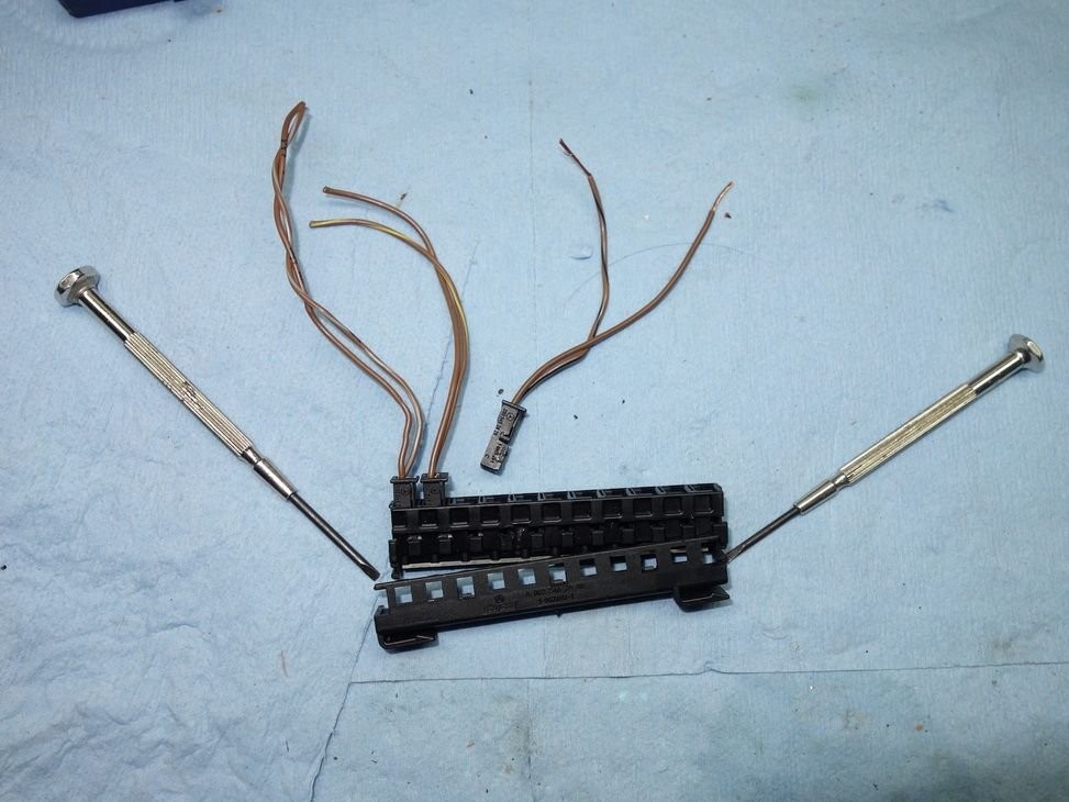
- Prepare Diagnostic Connectors: Obtain a compatible junction block connector for diagnostic purposes. Used parts can often be sourced online. Carefully remove a connector from the used block, ensuring not to damage the pins or wiring.
- Access CAN Bus Lines: With the X30/7 junction block exposed, you’ll see multiple connectors. Carefully insert your prepared diagnostic connector into the designated diagnostic slot. The W210 typically uses ten of the eleven slots in the X30/7 block, leaving one slot open for diagnostic connection.
- Connect a Multimeter: Attach a multimeter to the diagnostic connector to measure CAN High (CAN Hi) and CAN Low (CAN Lo) voltage levels.
Important Note: When working with the X30/7 junction block, meticulous attention to connector placement is crucial. Each connector position corresponds to a specific component or system on the CAN bus network. Swapping connectors can lead to misdiagnosis and further complications. Always refer to the W210 CAN bus schematic for correct connector identification.
Diagnosing CAN Bus Issues: A Practical Example
Consider a scenario where you experience failures in front door control modules (DCM) and the lower control panel (LCP) in your W210. Symptoms might include inoperative front windows, side mirrors, seat adjustments, and steering wheel adjustments, while rear windows and the sunroof still function correctly. This type of issue can often point to a CAN bus communication problem.
Using the X30/7 junction block method described above, you can systematically investigate such CAN bus failures. By measuring voltages at different connector positions, you can identify deviations from expected values and pinpoint the source of the problem.
For instance, in the example case, initial voltage readings at positions 1 (LCP), 6 (left front DCM), and 8 (right front DCM) revealed abnormalities.
Comparing measured voltages to the expected values in both “Sleep” (key off) and “Awake” (key in position 1) states is essential. The following schematic and voltage chart are invaluable for this process:
By systematically disconnecting and reconnecting CAN bus connectors one at a time while monitoring voltage changes, you can isolate the circuit causing the fault. In the example provided, removing connector 7 (left rear door) surprisingly stabilized the CAN bus voltages.
Identifying the Root Cause: A Faulty Window Motor
Further investigation revealed a short to ground on the CAN High (CAN Hi) line specifically when the left rear door connector was attached. This led to the discovery of a faulty electric window motor in the left rear door, which was unexpectedly interfering with the entire CAN bus system.
Replacing the faulty window motor (part number 210-820-53-42) resolved the CAN bus issue, restoring proper functionality to the door control modules and related systems.
Conclusion
Diagnosing CAN bus problems on a W210 Mercedes-Benz requires a slightly different approach than newer vehicles due to the OBD2 port’s limited CAN bus access. By understanding the w210 obd2 location and its constraints, and by utilizing the X30/7 junction block for direct CAN bus diagnostics, you can effectively troubleshoot and repair complex electrical issues. This guide, along with the practical example of a faulty window motor disrupting the CAN bus, aims to equip W210 owners and DIY mechanics with valuable knowledge for maintaining these classic Mercedes-Benz vehicles.
