For automotive enthusiasts and DIYers, accessing your vehicle’s diagnostic data can unlock a deeper understanding of its health and performance. While professional scan tools offer comprehensive features, sometimes a simple, homemade solution is all you need for basic diagnostics. This guide will walk you through creating your own Usb Wiring Diagram Homemade Obd2 To Usb Cable, allowing you to connect your car’s OBD2 port to a USB interface for basic troubleshooting and data access.
This project is designed for individuals comfortable with basic electronics and wiring. Please be aware that modifying your car’s wiring system carries inherent risks. While this guide aims for clarity and accuracy, you proceed at your own risk. We are not responsible for any damage to your vehicle or equipment resulting from following these instructions. Ensure you understand the basics of automotive electrical systems and proceed with caution.
Tools and Parts You’ll Need:
Before starting, gather the necessary tools and components to ensure a smooth build process.
- Wire Strippers/Cutters: Essential for preparing wires by removing insulation.
- Needle-Nose Pliers: Helpful for manipulating small components and wires, especially during crimping and connector assembly.
- Molex Crimping Tool (Optional but Recommended): While not strictly required, a crimping tool designed for Molex connectors will provide a more secure and professional connection.
- Soldering Iron (Recommended): Soldering provides a robust and reliable electrical connection, especially for fine wires.
- 4-Pin Connector: This connector will serve as the interface point for your USB adapter. Ensure it is compatible with the wire gauge you’ll be using. A suitable option is a 4-pin connector with pin/wire size compatibility for 22-16AWG and insulation/seal size for 1.3-1.7mm, such as those from Corsa Technic.
- OBD-II Cable: You’ll need an OBD-II cable with a female connector. This cable will interface with your vehicle’s OBD2 port. Consider using a pre-made OBD-II cable for convenience, or source the female OBD-II connector separately if you have spare wires.
For cost savings, if you have spare automotive-grade wire, you can purchase just the female OBD-II connector and wire it directly to the 4-pin connector. However, ensure you select the correct 4-pin connector and pins compatible with your wire gauge.
Understanding the OBD2 Connector Wiring Diagram for USB Conversion
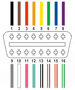
The OBD-II connector (OBD2C) has 16 pins, but for basic CAN bus communication over USB, we only need to utilize four key pins. This usb wiring diagram homemade obd2 to usb cable focuses on these essential connections:
- Pin 4 (Chassis Ground): Provides a ground reference for the circuit. Typically an orange wire on the OBD2C.
- Pin 6 (CAN High – J-2234): Carries the CAN bus high signal. Usually a green wire on the OBD2C.
- Pin 14 (CAN Low – J-2234): Carries the CAN bus low signal. Often a brown wire with a white stripe on the OBD2C.
- Pin 16 (Battery Power): Supplies power to the OBD-II interface. Commonly a green wire with a white stripe on the OBD2C.
Step-by-Step Guide to Building Your Homemade OBD2 to USB Cable
Let’s proceed with the construction of your homemade obd2 to usb cable.
Step 1: Preparing the OBD-II Cable Wires
Begin by carefully preparing the OBD-II cable. In many DIY guides, twisting wire pairs is recommended to reduce electromagnetic interference and improve signal integrity. We’ll follow this best practice.
- Remove Sheath and Shielding: Carefully use your wire strippers or cutters to remove the outer sheath and any shielding material from the OBD-II cable, exposing the individual wires inside.
- Separate the Four Essential Wires: Identify and separate the four wires corresponding to pins 4, 6, 14, and 16 as listed in the usb wiring diagram homemade obd2 to usb cable section above.
- Isolate Unused Wires: Bundle the remaining 12 wires (that we won’t be using) and secure them with a zip tie to keep them organized and out of the way during the build process.
Step 2: Preparing the 4-Pin Connector Wires
The wires in many OBD-II cables are often very thin (e.g., 26AWG). If your 4-pin connector pins are designed for a slightly thicker wire gauge (e.g., 22AWG), you’ll need to adapt the OBD-II cable wires for a secure connection.
- Strip Additional Wire Insulation: The OBD-II cable wires likely come pre-stripped with a short length of exposed wire (around 1/8 inch). Carefully strip off more insulation to expose approximately 3/8 inch of wire.
- Thicken the Wire (If Necessary): To ensure a better fit within the 4-pin connector pins, fold the exposed wire over itself and twist the folded wire to effectively double its thickness. This will help create a more secure crimp or solder joint.
- Slide Rubber Seals: The 4-pin connector kit typically includes rubber seals. Slide one rubber seal onto each of the four prepared wires. These seals will provide environmental protection for the connection.
Step 3: Attaching Wires to 4-Pin Connector Pins
Now, we’ll attach the prepared wires to the pins of the 4-pin connector.
- Insert Wire into Pin: Observe the 4-pin connector pins. They typically have two sets of prongs. The front set is designed to crimp onto the exposed wire, and the rear set crimps onto the rubber seal. Insert the exposed wire into the front portion of the pin, ensuring it aligns with the front prongs. The wire may appear small compared to the pin connector at this stage.
- Secure Wire for Soldering/Crimping: Due to the small wire gauge, using needle-nose pliers to hold the wire in place against the pin connector can be helpful for the next step, especially if you plan to solder.
Step 4: Soldering the Wires (Recommended)
Soldering is highly recommended for creating a durable and electrically sound connection, particularly with thin wires.
- Solder Wire to Pin: Carefully solder the wire to the pin connector. Ensure the solder joint is clean and makes good contact with both the wire and the pin. If you’re new to soldering, numerous online resources like YouTube tutorials can provide helpful tips and techniques for soldering wires effectively.
Step 5: Crimping the Pins (Alternative Method)
If you prefer not to solder or have a Molex crimping tool, you can crimp the pins onto the wires.
- Crimp Front Prongs: If you have a Molex crimping tool, use it to crimp the front prongs of the pin connector securely onto the wire.
- Manual Crimping (Without Tool): If you don’t have a crimping tool, needle-nose pliers can be used. Carefully and gradually fold one of the front prongs over the wire using the pliers, then repeat for the other prong. Use a YouTube video as a visual guide for manual crimping techniques if needed.
- Optional Over-Crimping: For added security, you can gently use pliers to further flatten the crimped prongs, ensuring a tight grip on the wire. However, avoid excessive force that could damage the connector.
Step 6: Crimping the Seal Prongs
After securing the wire, crimp the rear prongs of the connector pin onto the rubber seal for strain relief and environmental protection.
- Slide Seal into Position: Slide the rubber seal up the wire until it is positioned between the rear prongs of the connector pin.
- Crimp Rear Prongs: Use the same crimping technique (either with a tool or pliers) to fold the rear prongs over the rubber seal, securing it in place.
Step 7: Twisting Wire Pairs (Recommended)
As mentioned earlier, twisting wire pairs is a recommended practice to minimize interference.
- Pair and Twist Wires: Pair the wires according to these combinations and twist each pair together:
- Pin 4 (orange) / Pin 16 (green w/white stripe) – Power and Ground Pair
- Pin 6 (green) / Pin 14 (brown w/white stripe) – CAN Bus Signal Pair
Step 8: Inserting Pins into the 4-Pin Connector Housing
Finally, insert the assembled pins into the 4-pin connector housing in the correct orientation, following the usb wiring diagram homemade obd2 to usb cable pinout.
-
Pin Insertion Order: Insert the pins into the 4-pin connector housing according to this pinout:
- Pin 14 (brown w/white stripe) > Connector Slot A
- Pin 6 (green) > Connector Slot B
- Pin 16 (green w/white stripe) > Connector Slot C
- Pin 4 (orange) > Connector Slot D
-
Lock Pins into Housing: Insert each pin into the rear of the connector housing until it clicks into place. You should hear a distinct click indicating that the pin is securely locked. Needle-nose pliers can be helpful for gently pulling the wire from the front to ensure the pin is fully seated and locked.
Completion and Testing
Congratulations! You have now completed your homemade obd2 to usb cable!
Before using your cable for critical tasks, it’s essential to test it. A basic test can involve connecting it to your vehicle and a compatible OBD-II software application to check for connectivity and data retrieval.
Important Considerations and Disclaimer:
Remember, this usb wiring diagram homemade obd2 to usb cable is intended for basic DIY diagnostics and educational purposes. For professional-level diagnostics, consider using dedicated, commercially available scan tools.
Disclaimer: This guide is for informational purposes only. Building and using this cable involves working with automotive electrical systems, which can be complex and potentially hazardous. Proceed at your own risk. We are not responsible for any damage or issues arising from the use or misuse of this information or the homemade cable. Always double-check your wiring and connections before connecting to your vehicle. If you are unsure about any step, consult with a qualified automotive technician.