Motorcycle maintenance and diagnostics have entered a new era, and for Yamaha owners, the ability to tap into your bike’s onboard computer is now more accessible than ever. While professional diagnostic tools exist, building your own Obd2 Yamaha adapter is a rewarding DIY project that can save you money and deepen your understanding of your motorcycle. This guide will walk you through the process of creating a simple OBD2 adapter, allowing you to read diagnostic codes and monitor your Yamaha’s performance.
Tools and Parts You’ll Need
Before you begin, gather these essential tools and parts. Having everything ready will streamline the build process.
- Wire strippers/cutters: For preparing the wires to make connections.
- Needle-nose pliers: Helpful for manipulating small parts and ensuring secure connections.
- Molex crimping tool (optional but recommended): For creating professional-grade crimped connections. If you prefer soldering, this isn’t strictly necessary.
- Soldering iron (recommended): Provides a robust and reliable electrical connection.
- 4-pin connector: This connector will interface with your Yamaha’s diagnostic port. (Link to part used; pin/wire size = 22-16AWG; insulation/seal size = 1.3-1.7mm)
- OBD-II Cable: This cable provides the standard OBD2 connector to interface with diagnostic scanners. (Link to part used)
If you have spare wires and wish to reduce costs, you can purchase just the female OBD-II connector and use your own wires to connect it to the 4-pin connector. Ensure your wire gauge is compatible with the 4-pin connector pins (22-16AWG).
Step-by-Step Guide to Building Your OBD2 Yamaha Adapter
This guide details each step to assemble your OBD2 Yamaha adapter. Follow these instructions carefully to ensure proper functionality.
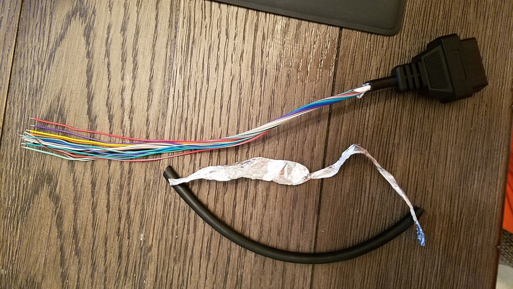
Step 1: Preparing the OBD2 Cable Wires
The OBD-II connector cable (OBD2C) contains 16 wires, but for this Yamaha OBD2 adapter, we only need four. These are the crucial wires for diagnostic communication:
- Pin 4 (Chassis ground): Orange wire on the OBD2C. Provides the ground connection.
- Pin 6 (CAN [J-2234] High): Green wire on the OBD2C. Carries the CAN bus high signal.
- Pin 14 (CAN [J-2234] Low): Brown with white stripe wire on the OBD2C. Carries the CAN bus low signal.
- Pin 16 (Battery power): Green with white stripe wire on the OBD2C. Provides power to the OBD2 adapter.
Start by carefully removing the outer sheath and shielding from the OBD2C to expose the wires. Separate these four required wires from the rest. Bundle the remaining 12 unused wires and secure them with a zip tie to keep them out of the way and prevent accidental shorts.
Step 2: Preparing the 4-Pin Connector Wires
The wires within the OBD2C are 26AWG, which is slightly thinner than the ideal size for the 4-pin connector (4PC) pins designed for 22AWG wires. To compensate for this difference and ensure a secure connection, we’ll “thicken” the wire ends.
The OBD2C wires come pre-stripped with a short exposed length. Increase the exposed wire length to approximately 3/8 inch. Fold this exposed wire section over itself, effectively doubling its thickness, and twist the folded wire to maintain a compact form.
The 4PC kit includes rubber seals. Slide one rubber seal onto each of the four prepared wires. These seals will provide environmental protection to the final connection.
Step 3: Attaching Pins to Wires
The pins for the 4PC have two sets of prongs. The front prongs are designed to crimp onto the exposed wire, while the rear prongs crimp onto the wire insulation (or in our case, the rubber seal).
Insert the prepared wire into a pin, aligning the wire with the front prongs. Due to the thin gauge of the wire, using needle-nose pliers to hold the wire in place during the next step is helpful.
Step 4: Soldering (or Crimping) the Connections
At this stage, you can choose to either solder or crimp the wire to the pin. Soldering provides a very secure and electrically sound connection, which is recommended, especially given the small wire size. If you prefer crimping and have a Molex crimping tool, that is also a viable option.
Soldering: If soldering, apply solder to the area where the wire meets the front prongs of the pin. Ensure the solder flows smoothly and creates a solid bond.
Crimping (Alternative): If crimping, use a Molex crimping tool to carefully crimp the front prongs around the wire. If you don’t have a crimping tool, needle-nose pliers can be used cautiously to fold over the prongs. Ensure a tight crimp for good electrical contact.
Step 5: Securing the Rubber Seal
Slide the rubber seal up the wire until it sits between the rear prongs of the pin. Use pliers to fold these rear prongs over the rubber seal, securing it in place. This provides strain relief and environmental sealing for the connection.
Step 6: Wiring Configuration and Pin Insertion
Pair the wires as follows, twisting each pair together. This is often recommended to minimize electrical noise and improve signal integrity:
- Pair 1: Pin 4 (orange) and Pin 16 (green w/white stripe)
- Pair 2: Pin 6 (green) and Pin 14 (brown w/white stripe)
Insert the completed pins into the 4PC in the correct orientation. Refer to the diagram below and insert the pins into the rear of the connector until they click into place. You should hear an audible click confirming they are locked. The pin assignments are:
- Connector slot A: Pin 14 (brown w/white stripe) – CAN Low
- Connector slot B: Pin 6 (green) – CAN High
- Connector slot C: Pin 16 (green w/white stripe) – Battery Power
- Connector slot D: Pin 4 (orange) – Chassis Ground
Testing Your OBD2 Yamaha Adapter
Congratulations! Your DIY OBD2 Yamaha adapter is now complete. Connect it to your Yamaha motorcycle’s diagnostic port and then to an OBD2 scanner or diagnostic tool. You should now be able to read diagnostic trouble codes (DTCs), clear codes, and access live data from your motorcycle’s ECU.
Important Considerations and Disclaimer
Disclaimer: This guide is for informational purposes only. Motorcycle repair and diagnostics should be undertaken with caution. While this DIY OBD2 Yamaha adapter has been shown to work, there’s always a risk involved in modifying your motorcycle’s electrical system. Ensure you double-check all connections and wiring before use. If you are not comfortable with electrical work or motorcycle diagnostics, consult a qualified professional. We are not responsible for any damage that may occur as a result of following this guide.
Compatibility: This adapter is designed for Yamaha motorcycles that utilize an OBD2-compatible diagnostic system with a 4-pin diagnostic port. Compatibility may vary between Yamaha models and years. Verify your motorcycle’s diagnostic port type and OBD2 compatibility before proceeding.
Software/Scanners: You will need a compatible OBD2 scanner or software to read data from your Yamaha ECU. Ensure your scanner or software supports motorcycle diagnostics and the CAN bus protocol.
Building your own OBD2 Yamaha adapter is a fantastic way to gain deeper insights into your motorcycle’s health and performance. With careful assembly and attention to detail, you can create a valuable tool for DIY maintenance and diagnostics.