Navigating the intricacies of your vehicle’s wiring can seem daunting, especially when dealing with the complex systems of modern cars. The OBD2 (On-Board Diagnostics II) system is a crucial part of your vehicle’s electronics, monitoring various aspects of engine performance and emissions. When modifying your vehicle, such as performing an engine swap or transmission upgrade, understanding your Obd2 Wiring Harness Diagram becomes indispensable. This guide will clarify the essential components and wiring considerations, particularly focusing on common modifications and wire removals within Ford Explorer OBD2 systems.
Key Components of an OBD2 Wiring Harness
An OBD2 wiring harness is a network of wires connecting the engine control unit (PCM or Powertrain Control Module) to various sensors, actuators, and components throughout your vehicle. For modifications, specifically on Ford Explorer models, certain connectors and PCM pins are crucial to understand. We will focus on the C115 connector and specific PCM pin functions that are frequently addressed during engine swaps or when simplifying the wiring system.
C115 Connector Wiring
The C115 connector is a significant point in the wiring harness, often located in the engine bay. Pin assignments within the C115 can sometimes be inconsistent or poorly documented. However, understanding certain wires within this connector is essential, particularly for neutral safety switch (NSS) and reverse light wiring.
-
Neutral Safety Switch (NSS) Wiring:
- Pink Wire (NSS In): This wire carries the start signal from your ignition switch.
- Red/Blue (96-97) or Tan/Red (98+) Wire (NSS Out): This wire sends the start signal to the starter solenoid, enabling the engine to crank only in Park or Neutral.
-
Reverse Light Wiring:
- Purple/Orange Wire (Reverse Light Switch In): This wire should be connected to a fused (10 amp) power source that is hot in the “Run” position.
- Black/Pink Wire (Reverse Light Switch Out): This wire provides power to your reverse lights when the reverse light switch is activated.
Important Note on Red/White Wire (Pin #33): If you find a red/white wire at pin #33 of your C115 connector, it’s recommended to remove it from both sides of the connector. This wire, often related to transmission harnesses, is typically unnecessary and can cause confusion during wiring modifications.
4R70W Transmission Considerations: If you are not using a 4R70W transmission, all the NSS and reverse light wires mentioned above can be removed from your harness. If you are retaining the 4R70W, you can either keep these wires and route them to the transmission harness, or, if these circuits are already present in your body harness near the transmission, you can de-pin them at the C115 connector.
PCM Pinout and Wire Removal
The PCM pinout diagram is critical when streamlining your OBD2 wiring harness. For those removing features like EVAP, air conditioning, EGR, or rear O2 sensors during modifications, certain PCM pins become redundant and their wires can be safely removed. However, it is crucial to ONLY remove wires from the PCM pins listed below and to double-check any footnotes provided. Any PCM wires not explicitly listed here MUST be retained for proper vehicle operation.
-
EVAP (Evaporative Emission Control System): The Explorer EVAP system is complex and often removed in engine swap scenarios.
- 12- Yellow/White
- 56- Lt Green/Black
- 62- Red/Pink
- 67- Purple/white***
Note on EVAP Purge Solenoid (Optional): For simplified EVAP setups (similar to Fox Mustang systems), pin 56 (Lt Green/Black) can be wired to one side of a purge solenoid, with the other side connected to a “hot in run” power source. However, this configuration is untested in vehicles and is at your own discretion.
-
Air Conditioning (A/C): The following pin removals are applicable if you are not using A/C or if you are bypassing PCM control of the A/C relay for simpler wiring.
- 41- Dark Green/Orange or Purple*** (A/C request signal input – can be repurposed for a high idle switch)
- 69- Pink/Yellow (PCM control wire for A/C relay – removed when bypassing PCM control)
- 86- Black/Yellow (Ground for A/C or high idle switch in bypassed configuration)
***Note on Pin 41 and 67 Color Swap: On later harnesses where pin 41 is purple, it is recommended to swap pin 67 (Purple/white) to the pin 41 location. This helps avoid confusion with duplicate purple wire colors when simplifying the harness.
-
EGR (Exhaust Gas Recirculation):
- 47- Brown/Pink – +++
- 63- Orange/ Yellow
- 65- Brown/Lt Green
+++ Resistor Installation (96 Harnesses): When removing EGR on 1996 harnesses specifically, a resistor needs to be installed at pin 47 (Brown/Pink) to simulate the EGR system for the PCM and prevent error codes.
-
VSS (Vehicle Speed Sensor): Refer to the VSS flowchart diagram (provided below) to determine if VSS wiring is necessary for your application.
- 33- Pink /Orange – VSS-
- 58- Grey/Black- VSS +
-
Miscellaneous Unused Pins:
- 14- Lt Blue/Black
- 19- Orange/Black
- 43- Lt Blue/Pink
-
Rear O2 Sensors: If rear O2 sensors are not needed for your application (e.g., running long tube headers and disabling rear O2s in tuning), these pins can be removed.
- 35- Red/Lt Green
- 61- Purple /Lt Green
- 95- White/Black
- 96- Tan/Yellow
-
4R70W Transmission (Specific Pins): These PCM pins are specifically for controlling the 4R70W transmission. If you are not using an electronic transmission controlled by this PCM, these wires can be removed.
- 1- Purple/Orange
- 3- yellow/Black
- 27- Orange/Yellow
- 29- Tan/White- (Overdrive switch)
- 37- Orange/Black
- 49- Lt Blue/Black
- 50- White/Black
- 54- Dark Blue/White
- 64- Lt Blue/Yellow
- 79- White/ Lt Green- (Overdrive Off Light)
- 81- White/Yellow
- 84- Dark Blue/Yellow
4R70W Transmission Swap Considerations
When swapping to a 4R70W transmission, particularly upgrading from an earlier (96-97) to a later (98+) model, there are two key points to consider to ensure compatibility with your OBD2 wiring harness and PCM.
-
Transmission Range Sensor Compatibility: The transmission range sensor MUST be compatible with your PCM year. 96 PCMs require a 96 range sensor, and 97-01 PCMs require a 97-01 range sensor. Be aware that some 97 models might have used 96 components, so always refer to your PCM code as the definitive reference.
-
Transmission Plug Repinning: The wiring configuration of the transmission plug differs between early and late 4R70W transmissions. You will need to repin the transmission plug to match the year of your transmission. When upgrading to a 98+ transmission on an earlier harness, repinning the plug and removing two unused power wires is necessary. Conversely, using an early transmission on a later harness requires adding two power wires (rear O2 heater circuit wires can be repurposed for this).
Image alt text: 4R70W Transmission Plug Wiring Diagram Comparison: 96-97 vs 98+ models, showing pinout differences for engine swap harness modification.
Image alt text: 98+ 4R70W Transmission Plug Wiring Diagram: Pin assignments and wire colors for harness modification and vehicle integration.
Note on Pin 4 (98+ Trans Plug): Pin 4 on the 98+ transmission plug is often blue/orange, despite diagrams sometimes indicating red.
Essential Wiring Diagrams for Modifications
Visual diagrams are invaluable when working with your OBD2 wiring harness. Here are crucial diagrams for alternator, starter solenoid, power distribution, and VSS wiring.
Alternator Wiring Diagram (3G/4G)
This diagram is for a 3G alternator, but Explorers typically use a 4G alternator. The primary wiring difference is that 4G alternators lack the white/black wire. The charge light wiring is optional. If omitted, providing a “hot in run” power source to the green/red wire will excite the alternator. Often, a suitable green/red wire can be found at the original fender-mounted voltage regulator.
Image alt text: 3G Alternator Wiring Diagram: Illustrating connections for battery, ignition, and charge light in OBD2 harness modifications, suitable for understanding 4G variations.
Starter Solenoid Wiring Diagram
This diagram illustrates how to wire the starter solenoid to function with an Explorer starter. Maintaining a fender-mounted solenoid is recommended, especially with later harnesses that have thinner start circuit wiring. If you are not using a 4R70W, your existing Bronco wiring can feed the “S” terminal on the solenoid. With a 4R70W, use the red/blue or tan/red wire (depending on year) to feed the “S” terminal.
Image alt text: Starter Solenoid Wiring Diagram: Detailing connections for battery, starter, ignition switch, and ground, essential for Ford Explorer engine swap wiring.
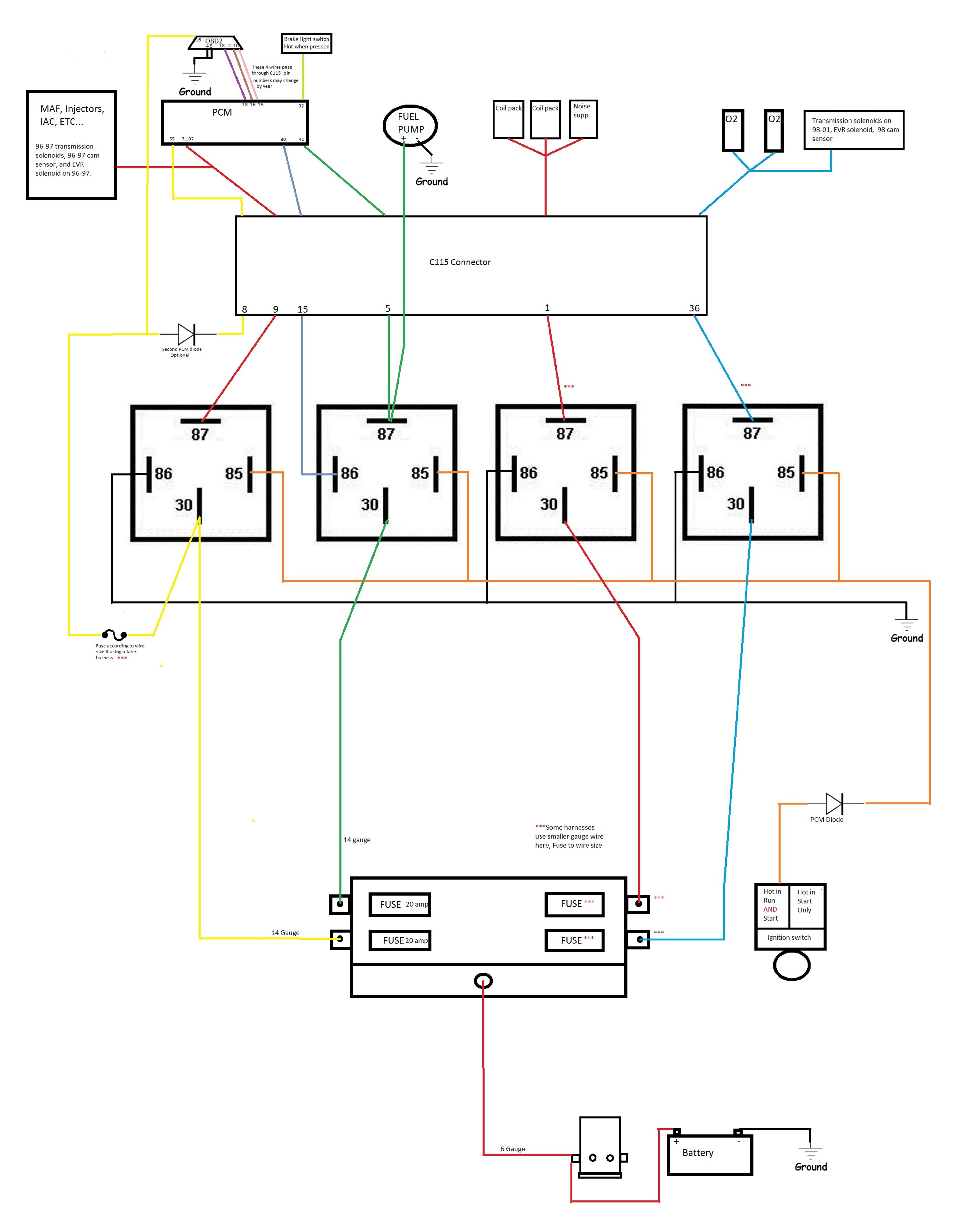
Power Distribution Diagram
This basic power distribution diagram outlines a common approach for managing power in modified OBD2 systems.
VSS Wiring Diagram
Refer to these VSS diagrams to understand the wiring and signal flow for your vehicle speed sensor, crucial if retaining speed-sensitive functions.
Conclusion
Understanding your obd2 wiring harness diagram is crucial for successful automotive modifications, particularly engine swaps and transmission upgrades. By carefully identifying and, when appropriate, removing unnecessary wires, and by correctly wiring essential components like the alternator, starter, and transmission, you can streamline your vehicle’s electrical system and ensure reliable operation. Always refer to wiring diagrams and your vehicle’s specific documentation to ensure accuracy and safety when working with your OBD2 wiring harness.