For automotive enthusiasts, mechanics, and DIYers, accessing a vehicle’s onboard computer data opens up a world of possibilities. The On-Board Diagnostics II (OBD-II) system is a standardized system that provides real-time data about a vehicle’s health and performance. To tap into this valuable information and interface it with microcontrollers like Arduino, the Obd2 Uart Adapter emerges as a crucial tool. This article provides an in-depth look at the OBD2 UART adapter, its features, capabilities, and how it empowers you to interact with your vehicle’s data.
What is an OBD2 UART Adapter?
An OBD2 UART adapter acts as a bridge, seamlessly translating the complex communication protocols of your car’s OBD-II port into a simple, universally understood UART (Universal Asynchronous Receiver/Transmitter) serial interface. Think of it as a translator that allows your Arduino, Raspberry Pi, or other microcontroller to “speak the language” of your car’s computer. This adapter plugs directly into your vehicle’s OBD-II port, typically located under the dashboard, and provides a serial data stream that can be easily processed and utilized for various applications, from vehicle diagnostics to custom data logging and performance monitoring.
Key Features and Benefits of the OBD2 UART Adapter
The OBD2 UART adapter is packed with features designed to make accessing vehicle data straightforward and efficient for a range of users, from hobbyists to professional mechanics.
Universal OBD-II Access and ELM327 Compatibility
At its core, the adapter is designed to access all standard OBD-II PIDs (Parameter IDs). It utilizes the popular ELM327 AT command set, a widely recognized standard in the OBD-II world. This compatibility ensures broad vehicle support and simplifies communication, allowing users to leverage existing knowledge and resources related to ELM327 commands. This means you can use readily available software and libraries designed for ELM327 devices, streamlining your projects and reducing development time.
Vehicle Diagnostics and Data Acquisition
Beyond basic data access, the OBD2 UART adapter empowers users to perform real vehicle diagnostics. It supports reading and clearing diagnostic trouble codes (DTCs) related to the engine and powertrain. This feature is invaluable for troubleshooting car problems, understanding error codes, and even performing basic repairs. Furthermore, the adapter facilitates comprehensive data acquisition, enabling users to monitor a wide array of vehicle parameters in real-time, including engine RPM, coolant temperature, vehicle speed, and much more. This data can be used for performance analysis, fuel efficiency monitoring, and creating custom dashboards.
Advanced Motion Sensing and Orientation
A standout feature of many OBD2 UART adapters is the integration of a 9-DOF (Degrees of Freedom) motion sensor, often the MPU-9250. This sensor, combined with a built-in sensor fusion algorithm, allows the adapter to detect motion, acceleration, gyroscope readings, and even orientation. This opens up exciting possibilities for applications like vehicle tracking, accident detection, and advanced telemetry systems. Imagine building a system that not only logs engine data but also records driving dynamics and vehicle orientation.
Versatile Connectivity and Power Supply
The OBD2 UART adapter is designed for seamless integration with microcontrollers. It offers serial UART compatibility with both 3.3V and 5V microcontrollers, ensuring compatibility with a wide range of development boards, including Arduino. The adapter also provides a regulated 5V power output, capable of delivering up to 2.1A, which is sufficient to power connected devices like Arduino boards, eliminating the need for separate power supplies and simplifying wiring. For direct computer or tablet connection, a Micro USB port is also included, providing another avenue for data access and potentially power output.
Compatibility and Vehicle Protocol Support
The OBD2 UART adapter is designed to be broadly compatible with OBD-II compliant vehicles. OBD-II is a standard mandated in most cars manufactured after 1996 in the USA, 2001 in Europe, and 2006 in Asia. To quickly check if your vehicle is OBD-II certified, look for a sticker under the hood, often near the radiator or engine bay. This sticker will explicitly state OBD-II compliance.
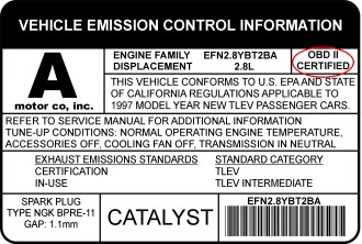 obd_sticker
The OBD2 UART adapter supports a comprehensive range of vehicle communication protocols, ensuring compatibility with a vast majority of OBD-II compliant vehicles. These protocols include:
- CAN 500Kbps/29bit
- CAN 500Kbps/11bit
- CAN 250Kbps/29bit
- CAN 250Kbps/11bit
- KWP2000 Fast
- KWP2000 5Kbps
This multi-protocol support makes the OBD2 UART adapter a versatile tool for various vehicle makes and models.
Connecting Your OBD2 UART Adapter
Connecting the OBD2 UART adapter is designed to be user-friendly. The adapter plugs directly into the OBD-II port in your car. Typically, this port is located under the steering column, but it can sometimes be found slightly to the left. Most adapters come with a cable that branches out to provide different connection options.
Connector Details
The connector typically splits into a 4-pin connector and two 2-pin connectors, providing access to power and data lines.
Power Connector (2-pin Dupont)
- Red Wire: VCC (Connect to Arduino’s 5V or VCC pin)
- Black Wire: GND (Connect to Arduino’s GND pin)
Serial UART Data Connector (2-pin Dupont)
- White Wire: Rx (Connect to Arduino’s serial Tx pin – D1 on Arduino Uno)
- Green Wire: Tx (Connect to Arduino’s serial Rx pin – D0 on Arduino Uno)
USB Port
- Micro USB port for connecting to a computer or tablet.
- Can also provide 5V/2A power output.
When connecting to Arduino Uno or Nano, be mindful that these boards only have one hardware serial port, which is shared with the USB connection. Avoid using serial output for debugging if the adapter is connected to the hardware serial pins. Arduino Leonardo, Mega, and Due have multiple hardware serial ports and do not have this limitation.
Extended AT Commands for Advanced Control
The OBD2 UART adapter goes beyond standard ELM327 commands by offering an extended AT command set. These extended commands provide access to advanced functionalities, including motion sensor data, orientation calculations, and specific control over different data buses.
Motion Sensor Access Commands
- ATACL: Reads accelerometer data in G-force units (X, Y, Z).
- ATGYRO: Reads gyroscope data in degrees per second (X, Y, Z).
- ATMAG: Reads magnetometer data in milli-Gauss (X, Y, Z).
- ATTEMP: Reads temperature data (raw sensor data).
Quaternion and Orientation Control
- ATQU0: Disables 9-DOF sensor fusion.
- ATQU1: Enables 9-DOF sensor fusion (default disabled).
- ATORI: Retrieves orientation parameters (roll, pitch, yaw) in degrees from the sensor fusion algorithm.
K-Line and ISO9141-2 Specific Commands
- ATSH: Sets header bytes for K-Line and ISO9141-2 communication (e.g.,
ATSH C1 33 F1). - ATPTH: Sets initializing pulse time (0-255ms in hex) for K-Line/ISO9141-2 (e.g.,
ATPTH 19for 25ms). - ATPTA: Sets negative pulse duration before the first data byte (0-255ms in hex) for K-Line/ISO9141-2 (e.g.,
ATPTA 32for 50ms).
CAN Bus Sniffing Commands
- ATSH: Sets CAN message header for 11-bit CAN (e.g.,
ATSH 7DF). - ATSH: Sets lower 24 bits of CAN message header for 29-bit CAN (higher 5 bits set by ATCP, e.g.,
ATSH DB 33 F1). - ATCP: Sets CAN priority/higher 5 bits of header for 29-bit CAN (e.g.,
ATCP 18). - ATCF
: Sets CAN message header filter for CAN sniffing ( for 11-bit CAN, for 29-bit CAN, e.g., ATCF 7E8). - ATCM : Sets CAN message filtering bit mask (32-bit, e.g.,
ATCM FFFFFFFE). - ATM1: Starts CAN sniffing mode.
- ATM0: Stops CAN sniffing mode.
Examples of CAN Bus Sniffing
Typical sniffing on 11-bit 500kbps CAN bus:
ATSP6(Set protocol to CAN 11-bit 500kbps)ATCF 700(Set header filter to 0x700)ATCM FFFFFF00(Set mask to ignore the last byte of the header)ATM1(Start sniffing)
Typical sniffing on 29-bit 500kbps CAN bus:
ATSP7(Set protocol to CAN 29-bit 500kbps)ATCF 18DBF133(Set header filter to 0x18DBF133)ATCM FF000000(Set mask to ignore the first 3 bytes of the header)ATM1(Start sniffing)
Arduino Library and Example Applications
To simplify development with Arduino, a dedicated Arduino library is available for the OBD2 UART adapter. This library encapsulates many of the adapter’s functionalities into easy-to-use APIs, abstracting away the complexities of AT commands.
Commonly used Arduino library APIs include:
setBaudRate(): Sets the adapter’s serial baud rate.readPID(PID, value): Reads a specified OBD-II PID and returns the parsed value.clearDTC(): Clears diagnostic trouble codes.getVoltage(): Measures car battery voltage.getVIN(): Retrieves the Vehicle Identification Number.getTemperature(): Gets the adapter’s temperature.readAccel(x, y, z): Reads accelerometer X, Y, Z values.memsInit(): Initializes the motion sensor.memsRead(): Reads raw motion sensor data.memsOrientation(roll, pitch, yaw): Retrieves computed orientation data.
Here’s a simple example of an engine RPM indicator using the Arduino library and the built-in LED on pin 13:
#include <obd2uart.h>

COBD obd;

void setup() {
  // Use the debug LED as output
  pinMode(13, OUTPUT);
  // Start serial communication
  obd.begin();
  // Initiate OBD-II connection until success
  while (!obd.init());
}

void loop() {
  int value;
  // Save engine RPM in variable 'value', return true on success
  if (obd.readPID(PID_RPM, value)) {
    // Light on LED on Arduino board when the RPM exceeds 3000
    digitalWrite(13, value > 3000 ? HIGH : LOW);
  }
}
More example sketches are available in the library repository, demonstrating various functionalities and applications.
The OBD library also pre-defines commonly used PIDs, categorized for easy access:
Engine PIDs:
PID_RPM: Engine RPM (rpm)PID_ENGINE_LOAD: Calculated engine load (%)PID_COOLANT_TEMP: Engine coolant temperature (°C)PID_ABSOLUTE_ENGINE_LOAD: Absolute Engine load (%)PID_TIMING_ADVANCE: Ignition timing advance (°)PID_ENGINE_OIL_TEMP: Engine oil temperature (°C)PID_ENGINE_TORQUE_PERCENTAGE: Engine torque percentage (%)PID_ENGINE_REF_TORQUE: Engine reference torque (Nm)
Intake/Exhaust PIDs:
PID_INTAKE_TEMP: Intake temperature (°C)PID_INTAKE_PRESSURE: Intake manifold absolute pressure (kPa)PID_MAF_FLOW: MAF flow rate (grams/s)PID_BAROMETRIC: Barometric pressure (kPa)
Speed/Time PIDs:
PID_SPEED: Vehicle speed (km/h)PID_RUNTIME: Engine running time (second)PID_DISTANCE: Vehicle running distance (km)
Driver PIDs:
PID_THROTTLE: Throttle position (%)PID_AMBIENT_TEMP: Ambient temperature (°C)
Electric Systems PIDs:
PID_CONTROL_MODULE_VOLTAGE: Vehicle control module voltage (V)PID_HYBRID_BATTERY_PERCENTAGE: Hybrid battery pack remaining life (%)
Users can add additional PID definitions to access the full range of OBD-II PIDs supported by their vehicle’s ECU.
OBD2 UART Adapter Models Comparison
| Features | OBD-II UART Adapter V1 | OBD-II UART Adapter V2 | OBD-II UART Adapter V2.1 |
|---|---|---|---|
| Connection Cable | Fixed | Fixed | Unpluggable |
| Additional Interface | N/A | micro USB | micro USB |
| Motion Sensor | N/A | 6-DOF MPU-6050 | 9-DOF MPU-9250 |
| Voltmeter | Yes | Yes | Yes |
| Max. Output Power | 2A | 2.1A | 2.1A |
| Standby Power | 5mA | 6mA | 6mA |
Frequently Asked Questions
Q: What is the primary use of the OBD2 UART adapter?
A: The main purpose is to enable easy access to vehicle data for Arduino and similar microcontrollers. This facilitates creating open-source vehicle data loggers, custom dashboards, and various interactive automotive applications.
Q: How is the adapter powered?
A: The adapter draws power directly from the 12V DC supply available at the OBD-II port.
Q: Does my Arduino require external power when using the adapter?
A: No. The adapter provides a regulated 5V output, sufficient to power Arduino and other connected devices, eliminating the need for an external power source for your microcontroller.
Q: Do I need a separate CAN bus shield to use this adapter?
A: No. The OBD2 UART adapter internally handles the CAN bus interface. It retrieves data from the CAN bus and converts it into a simpler serial UART interface, which Arduino and most embedded systems can easily understand and utilize.
Q: How do I physically connect the adapter to my Arduino?
A: The adapter connects to Arduino via its UART data connector. Connect the adapter’s Tx pin (green wire) to Arduino’s Rx pin (D0) and the adapter’s Rx pin (white wire) to Arduino’s Tx pin (D1). For convenient connections and disconnections, consider using an I/O breakout shield or an Arduino board with breakout pins.
Q: Is the power from the adapter always on, even when the car is off?
A: This depends on your car’s OBD-II port power behavior. In many vehicles, the OBD-II port remains powered even after the ignition is turned off.
Q: What is the maximum data polling frequency I can achieve?
A: The data polling rate depends on the car’s ECU processing speed and busyness. With modern CAN bus vehicles, polling times can be as low as 10ms, potentially allowing up to 100 data polls per second.
Q: Can you provide support for Arduino programming?
A: While we provide resources and examples, comprehensive Arduino programming support is beyond our scope. Numerous online tutorials and guides are available for learning Arduino programming.
Q: What is the difference between product version and firmware version?
A: Product version refers to the hardware iteration (e.g., V1, V2, V2.1) of the OBD2 UART adapter. Firmware version refers to the software running on the adapter itself. For example, the OBD2 UART Adapter V2 uses firmware version 1.1, while V1 uses firmware version 1.0.
The OBD2 UART adapter is a powerful and versatile tool for anyone looking to access and utilize vehicle data. Whether you are a professional mechanic, a car enthusiast, or a DIY hobbyist, this adapter provides an accessible and efficient way to interact with your vehicle’s onboard systems, opening up a wide range of applications and possibilities in automotive diagnostics, data logging, and custom vehicle projects.