Looking for a straightforward and practical Obd2 Tutorial?
This comprehensive guide provides an in-depth introduction to the On-Board Diagnostic (OBD2) protocol, covering key aspects such as the OBD2 connector, OBD2 Parameter IDs (PIDs), and its integration with the CAN bus system.
Whether you’re a car enthusiast, a seasoned mechanic, or just curious about vehicle diagnostics, this OBD2 tutorial will equip you with the knowledge to understand and utilize OBD2 effectively. We focus on practical applications, teaching you how to request and decode OBD2 data, explore essential logging use cases, and offer valuable tips to get you started.
Discover why this article is considered a leading OBD2 tutorial for those seeking a clear and actionable understanding of vehicle diagnostics.
You can also watch our introductory OBD2 video above – or download our PDF guide for offline access.
Article Contents:
Author: Martin Falch (Updated January 2025)
Download this OBD2 tutorial as a PDF
Understanding OBD2: What is it?
OBD2, or On-Board Diagnostics version 2, is essentially your vehicle’s internal health monitoring system. It’s a standardized protocol designed to access diagnostic trouble codes (DTCs) and real-time vehicle data through the OBD2 connector. This system has become indispensable in modern automotive repair and diagnostics.
You’ve likely already encountered OBD2 in action. Ever seen the check engine light illuminate on your dashboard?
That light is your car signaling a potential issue. When you take your car to a mechanic, they use an OBD2 scanner to pinpoint the problem. This obd2 tutorial will help you understand how these scanners work.
The mechanic connects the OBD2 reader to the OBD2 16-pin connector, typically located near the steering wheel. The scanner sends ‘OBD2 requests’ to the vehicle, and the car responds with ‘OBD2 responses’. These responses can contain vital information such as speed, fuel level, or Diagnostic Trouble Codes (DTCs). This rapid data exchange allows for quicker and more efficient troubleshooting.
Image alt text: OBD2 system showing malfunction indicator light (MIL) and a mechanic using a scan tool to diagnose a car.
OBD2 Compatibility: Does Your Car Have It?
The simple answer is: Almost certainly, yes!
The vast majority of modern non-electric cars are equipped with OBD2 and utilize the CAN bus communication protocol. However, for older vehicles, the presence of a 16-pin OBD2 connector doesn’t guarantee OBD2 compliance. Some older cars with the connector might not fully support the OBD2 standard. A reliable way to check compliance is based on the vehicle’s purchase location and year:
Image alt text: Chart illustrating OBD2 compliance by region (US, EU) and vehicle type (car, light truck) over time, highlighting key mandate years.
A Look into OBD2 History
The origins of OBD2 trace back to California, where the California Air Resources Board (CARB) mandated OBD systems in all new vehicles starting from 1991 for emissions monitoring. This obd2 tutorial will help you understand the significance of this history.
The Society of Automotive Engineers (SAE) further developed the OBD2 standard, standardizing DTCs and the OBD connector across different vehicle manufacturers with the SAE J1962 specification.
The OBD2 standard was progressively implemented globally:
- 1996: OBD2 became mandatory in the USA for cars and light trucks.
- 2001: Required in the EU for gasoline cars.
- 2003: Extended to diesel cars in the EU (known as EOBD).
- 2005: OBD2 mandate in the US expanded to medium-duty vehicles.
- 2008: US vehicles were required to use ISO 15765-4 (CAN) as the foundation for OBD2.
- 2010: OBD2 compliance became mandatory for heavy-duty vehicles in the US.
Image alt text: Infographic depicting OBD2 history focusing on emission control, exhaust regulations, and the evolution towards EOBD2 and EOBDII standards.
Image alt text: Timeline visualization of OBD2 history, showing key dates and milestones in the development and adoption of on-board diagnostics.
Image alt text: Conceptual image representing the future of OBD3 with remote diagnostics, emissions testing, cloud connectivity, and IoT integration.
The Future of OBD2 and OBD3
OBD2 is firmly established, but its future evolution is actively being shaped. This obd2 tutorial section explores what’s next.
While originally conceived for emissions control and testing, OBD2 regulations don’t inherently apply to electric vehicles. As a result, most modern EVs do not support standard OBD2 requests. Instead, they often utilize OEM-specific UDS communication protocols. This shift makes accessing data from EVs challenging, except in cases where decoding methods have been reverse-engineered. Examples of successful reverse engineering are detailed in our case studies for electric cars, including Tesla, Hyundai/Kia, Nissan, and VW/Skoda EVs.
Recognizing the limitations of current OBD2 implementations in terms of data richness and lower-layer protocols, modern alternatives have emerged. These include WWH-OBD (World Wide Harmonized OBD) and OBDonUDS (OBD on UDS). Both aim to improve OBD communication by basing it on the UDS protocol. To delve deeper into these protocols, refer to our introduction to UDS.
In our increasingly connected world, traditional OBD2 testing methods can seem outdated. Manual emission control checks are time-consuming and costly.
The proposed solution is OBD3 – the integration of telematics into all vehicles.
OBD3 envisions adding a small radio transponder (similar to those used for bridge tolls) to every car. This would allow the car’s vehicle identification number (VIN) and DTCs to be wirelessly transmitted via WiFi to a central server for automatic checks.
Many current devices already facilitate CAN or OBD2 data transfer over WiFi/cellular networks, such as the CANedge2 WiFi CAN logger and the CANedge3 3G/4G CAN logger.
While offering cost and convenience benefits, OBD3 raises political and privacy concerns due to potential surveillance implications.
The original OBD2 protocol was primarily designed for stationary emission controls.
However, today, OBD2 is extensively utilized by third parties for real-time data generation via OBD2 dongles, CAN loggers, and similar tools. Interestingly, the German car industry is pushing for changes that could limit this third-party access German car industry plans close OBD interface.
As Christoph Grote, SVP Electronics at BMW, stated in 2017:
“OBD has been designed to service cars in repair shops. In no way has it been intended to allow third parties to build a form of data-driven economy on the access through this interface“
The proposal suggests deactivating OBD2 functionality during driving, centralizing data collection with manufacturers instead. This would give manufacturers control over the burgeoning ‘automotive big data’.
The rationale is rooted in security concerns, such as mitigating the risk of car hacking. However, many perceive this as a commercially motivated move. The future of this proposal and its potential to disrupt the third-party OBD2 service market remains to be seen.
Image alt text: Visual concept depicting the future trend of electric vehicles potentially blocking access to OBD2 data through connector removal.
Enhance Your CAN Bus Expertise
Want to become a CAN bus expert and further your OBD2 knowledge?
Access our 12 ‘simple intros’ compiled into a comprehensive 160+ page PDF:
Download the Ultimate CAN Bus Guide Now
OBD2 Standards Explained
On-board diagnostics, OBD2, is a higher-layer protocol, similar to a language, while CAN is the communication method, like a phone line. This analogy positions OBD2 alongside other CAN-based higher-layer protocols like J1939, CANopen, and NMEA 2000. This obd2 tutorial section clarifies these standards.
Specifically, OBD2 standards define the OBD2 connector, lower-layer protocols, OBD2 Parameter IDs (PIDs), and other crucial aspects.
These standards can be categorized within a 7-layer OSI model. The following sections will focus on the most critical standards.
In the OSI model representation, you’ll notice overlap between SAE and ISO standards. This generally reflects the standards originating from the USA (SAE) and the EU (ISO). Many standards are technically very similar, for instance, SAE J1979 and ISO 15031-5, or SAE J1962 and ISO 15031-3.
Image alt text: Diagram illustrating the relationship between OBD2 and CAN Bus within the 7-layer OSI model, highlighting ISO 15765 and ISO 11898 standards.
Image alt text: OBD2 Connector Pinout Socket Female Type A DLC diagram, detailing pin assignments for diagnostic data communication.
The OBD2 Connector [SAE J1962 / ISO 15031-3]
The 16-pin OBD2 connector is your gateway to accessing vehicle data, standardized under SAE J1962 / ISO 15031-3. This obd2 tutorial explains the connector details.
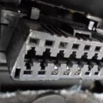
The illustration depicts a Type A OBD2 pin connector, also known as the Data Link Connector (DLC).
Key points to note:
- The connector is typically near the steering wheel but can sometimes be hidden from plain sight.
- Pin 16 provides battery power, often even when the ignition is off.
- The OBD2 pinout configuration varies based on the communication protocol used.
- CAN bus is the most prevalent lower-layer protocol, meaning pins 6 (CAN-H) and 14 (CAN-L) are commonly connected.
OBD2 Connector Types: A vs. B
You may encounter both Type A and Type B OBD2 connectors. Type A is standard in cars, while Type B is more common in medium and heavy-duty vehicles.
While both types share similar OBD2 pinouts, they differ in power supply outputs (12V for Type A and 24V for Type B) and often baud rates. Cars typically use 500K baud rate, whereas heavy-duty vehicles often use 250K (with increasing support for 500K more recently).
Type B OBD2 connectors have a distinctive interrupted groove in the middle, which visually differentiates them from Type A. Consequently, a Type B OBD2 adapter cable is compatible with both Type A and B sockets, but a Type A adapter will not fit into a Type B socket.
Image alt text: Diagram comparing OBD2 Connector Type A and Type B according to SAE J1962, highlighting differences in 12V and 24V power for cars, vans, and trucks.
Image alt text: Visual representation contrasting OBD2 and CAN bus in the context of ISO 15765 standards for automotive diagnostics and communication.
OBD2 and CAN Bus [ISO 15765-4 / ISO 11898]
Since 2008, CAN bus has been the mandatory lower-layer protocol for OBD2 in all vehicles sold in the US, as mandated by ISO 15765. This obd2 tutorial explains this critical link.
ISO 15765-4 (also known as Diagnostics over CAN or DoCAN) specifies a set of constraints applied to the CAN standard (ISO 11898).
It standardizes the CAN interface for diagnostic equipment, focusing on the physical, data link, and network layers:
- CAN bus bit-rate must be either 250K or 500K.
- CAN IDs can be 11-bit or 29-bit.
- Specific CAN IDs are designated for OBD requests and responses.
- Diagnostic CAN frame data length is fixed at 8 bytes.
- The OBD2 adapter cable must not exceed 5 meters in length.
OBD2 CAN Identifiers (11-bit, 29-bit)
OBD2 communication is based on request/response message exchanges. This obd2 tutorial section details the identifiers used.
In most passenger cars, 11-bit CAN IDs are used for OBD2 communication. The ‘Functional Addressing’ ID is 0x7DF, used to query all OBD2-compatible ECUs to check if they have data for the requested parameter (as per ISO 15765-4). CAN IDs in the range 0x7E0-0x7E7 can be used for ‘Physical Addressing’ requests to specific ECUs, although this is less common.
ECUs respond using 11-bit IDs in the range 0x7E8-0x7EF. The most frequent response ID is 0x7E8 (ECM, Engine Control Module), followed by 0x7E9 (TCM, Transmission Control Module).
In some vehicles, particularly vans and medium to heavy-duty vehicles, OBD2 communication may utilize extended 29-bit CAN identifiers instead of 11-bit IDs.
For 29-bit identifiers, the ‘Functional Addressing’ CAN ID is 0x18DB33F1.
Responses in 29-bit CAN ID systems range from 0x18DAF100 to 0x18DAF1FF (typically 18DAF110 and 18DAF11E). The response ID is sometimes represented in ‘J1939 PGN’ format, specifically PGN 0xDA00 (55808), which is reserved for ISO 15765-2 in the J1939-71 standard.
Image alt text: Diagram illustrating OBD2 protocol request and response frames, highlighting PID data parameters for diagnostic communication.
Image alt text: Conceptual illustration contrasting OBD2 standard CAN bus data with OEM-specific proprietary CAN bus data in vehicle systems.
OBD2 vs. Proprietary CAN Protocols
It’s crucial to understand that your vehicle’s electronic control units (ECUs) do not depend on OBD2 for their primary functions. Instead, each original equipment manufacturer (OEM) develops their own proprietary CAN protocols for internal vehicle communication. These protocols are often unique to the vehicle brand, model, and year. Accessing and interpreting this OEM-specific data is typically not possible without reverse engineering efforts or OEM tools. This obd2 tutorial clarifies the distinction.
When you connect a CAN bus data logger to your car’s OBD2 connector, you might observe OEM-specific CAN data, usually broadcast at a high rate of 1000-2000 frames per second. However, many newer vehicles incorporate a ‘gateway’ that restricts access to this proprietary CAN data via the OBD2 connector, only allowing OBD2 communication.
In essence, think of OBD2 as a supplemental higher-layer protocol that operates alongside the OEM-specific communication protocol.
Bit-rate and ID Validation
As discussed, OBD2 can operate with two bit-rates (250K, 500K) and two CAN ID lengths (11-bit, 29-bit), resulting in four possible combinations. Modern vehicles most commonly use 500K and 11-bit IDs. External diagnostic tools should systematically verify these parameters. This obd2 tutorial emphasizes validation.
ISO 15765-4 provides guidelines for a systematic initialization sequence to determine the correct combination, as illustrated in the flowchart. The method relies on the fact that OBD2-compliant vehicles must respond to a mandatory OBD2 request (see the OBD2 PID section for details) and that incorrect bit-rate transmissions will cause CAN error frames.
Newer versions of ISO 15765-4 account for vehicles that may support OBD communication through OBDonUDS rather than OBDonEDS. While this article primarily focuses on OBD2/OBDonEDS (OBD on Emission Diagnostic Service per ISO 15031-5/SAE J1979), as opposed to WWH-OBD/OBDonUDS (OBD on Unified Diagnostic Service per ISO 14229, ISO 27145-3/SAE J1979-2).
To differentiate between OBDonEDS and OBDonUDS protocols, diagnostic tools may include additional request messages, specifically sending UDS requests with 11-bit/29-bit functional address IDs for service 0x22 and data identifier (DID) 0xF810 (protocol identification). Vehicles supporting OBDonUDS must have ECUs that respond to this DID.
In practice, OBDonEDS (also known as OBD2, SAE OBD, EOBD, or ISO OBD) is predominantly used in non-EV cars today, while WWH-OBD is mainly found in EU trucks and buses.
Image alt text: Flowchart illustrating the OBD2 bit-rate and CAN ID validation process according to ISO 15765-4, guiding diagnostic tool initialization.
Image alt text: Diagram showcasing the five lower-layer OBD2 protocols: CAN (ISO 15765), KWP2000, SAE J1850, and ISO 9141, highlighting their roles in vehicle diagnostics.
Five Lower-Layer OBD2 Protocols
Today, CAN (ISO 15765) is the primary lower-layer protocol for OBD2 in most vehicles. This obd2 tutorial acknowledges older protocols as well.
However, when working with older vehicles (pre-2008), understanding the other four lower-layer protocols used for OBD2 is beneficial. Pinout configurations can often indicate which protocol is used in a specific vehicle.
- ISO 15765 (CAN bus): Mandatory in US vehicles since 2008 and now the most commonly used protocol.
- ISO14230-4 (KWP2000): Keyword Protocol 2000, frequently used in 2003+ vehicles, especially in Asia.
- ISO 9141-2: Used in EU, Chrysler, and Asian vehicles from 2000-2004.
- SAE J1850 (VPW): Predominantly used in older GM vehicles.
- SAE J1850 (PWM): Predominantly used in older Ford vehicles.
Transporting OBD2 Messages via ISO-TP [ISO 15765-2]
All OBD2 data transmission over CAN bus utilizes the ISO-TP (ISO 15765-2) transport protocol. This protocol is essential for transmitting data payloads exceeding the 8-byte CAN frame limit. ISO-TP is necessary in OBD2 for operations like retrieving the Vehicle Identification Number (VIN) or Diagnostic Trouble Codes (DTCs). It manages segmentation, flow control, and reassembly of larger messages. For a detailed explanation, refer to our introduction to UDS. This obd2 tutorial touches upon ISO-TP.
However, much of OBD2 data fits within a single CAN frame. In these cases, ISO 15765-2 specifies the use of ‘Single Frame’ (SF) format. The first data byte (PCI field) indicates the payload length (excluding padding), leaving 7 bytes for OBD2-related communication.
Image alt text: Diagram illustrating ISO 15765-2 ISO-TP OBD2 frame types, including Single Frame (SF), First Frame (FF), Consecutive Frame (CF), and Flow Control (FC).
Decoding the OBD2 Diagnostic Message [SAE J1979, ISO 15031-5]
To better understand OBD2 communication on CAN, let’s examine a raw ‘Single Frame’ OBD2 CAN message. In simplified terms, an OBD2 message consists of an identifier, a data length indicator (PCI field), and the data payload. The payload is further structured into Mode, Parameter ID (PID), and data bytes. This obd2 tutorial section breaks down the message structure.
Image alt text: Breakdown of the OBD2 message structure, explaining the components of a raw frame including Mode, PID, ID, and data bytes.
OBD2 Request/Response Example
Before detailing each part of the OBD2 message, consider this request/response example for ‘Vehicle Speed’. This obd2 tutorial provides a practical example.
An external tool sends a request message to the vehicle with CAN ID 0x7DF, containing 2 payload bytes: Mode 0x01 and PID 0x0D. The vehicle responds using CAN ID 0x7E8 with 3 payload bytes, including the Vehicle Speed value in the 4th byte, 0x32 (50 in decimal).
By consulting the decoding rules for OBD2 PID 0x0D, we determine that the physical value is 50 km/h.
The following sections will focus on OBD2 modes and PIDs in more detail.
Image alt text: Example of OBD2 request (CAN ID 7DF) and response (CAN ID 7E8) messages for retrieving vehicle speed.
Image alt text: OBD2 PID example specifically for Vehicle Speed (PID 0D), illustrating data encoding and decoding for this parameter.
Image alt text: Chart listing the 10 OBD2 services or modes, including current data, freeze frame, and clear DTC, which are essential diagnostic services.
The 10 OBD2 Services (Modes)
There are 10 standardized OBD2 diagnostic services, also referred to as modes. Mode 0x01 is used to access current real-time data, while other modes are designed to display and clear diagnostic trouble codes (DTCs) or show freeze frame data. This obd2 tutorial outlines these services.
Vehicles are not required to support all 10 OBD2 modes. They may also support additional OEM-specific modes beyond these standardized ones.
In OBD2 messages, the mode is specified in the second byte. In a request message, the mode is included directly (e.g., 0x01). In a response message, 0x40 is added to the mode value (e.g., resulting in 0x41).
OBD2 Parameter IDs (PIDs)
Within each OBD2 mode, there are Parameter IDs (PIDs). This obd2 tutorial explains PIDs.
For instance, mode 0x01 includes approximately 200 standardized PIDs that provide real-time data on parameters like speed, RPM, and fuel level. However, vehicles are not obligated to support all OBD2 PIDs within a mode. In practice, most vehicles only support a subset of these PIDs.
One PID is particularly significant:
If an emissions-related ECU supports any OBD2 services, it must support mode 0x01 PID 0x00. In response to PID 0x00, the vehicle ECU indicates whether it supports PIDs 0x01-0x20. This makes PID 0x00 a fundamental ‘OBD2 compatibility test’. Additionally, PIDs 0x20, 0x40, …, 0xC0 can be used to determine support for the remaining mode 0x01 PIDs.
Image alt text: Diagram again illustrating OBD2 protocol request and response frames, emphasizing PID data parameters for diagnostic communication.
Image alt text: Screenshot of an OBD2 PID overview tool, specifically for service 01, used for exploring and understanding supported PIDs.
Tip: OBD2 PID Overview Tool
The appendices of SAE J1979 and ISO 15031-5 provide scaling information for standard OBD2 PIDs. This scaling data allows you to decode raw data into physical values, as detailed in our CAN bus introduction. This obd2 tutorial recommends utilizing tools for PID lookup.
For quick lookups of mode 0x01 PIDs, our OBD2 PID overview tool is invaluable. It assists in constructing OBD2 request frames and dynamically decoding OBD2 responses.
Access the OBD2 PID overview tool here
Practical Guide: How to Log and Decode OBD2 Data
This section of our obd2 tutorial offers a practical example of logging OBD2 data using the CANedge CAN bus data logger.
The CANedge allows configuration of custom CAN frames for transmission, making it suitable for OBD2 logging.
Once configured, the CANedge can be easily connected to your vehicle using our OBD2-DB9 adapter cable.
Image alt text: Diagram showing an OBD2 PID data logger requesting data (7df) and receiving a response (7e8) for data logging purposes.
Image alt text: Screenshot from asammdf software displaying OBD2 validation PID test responses, reviewing supported PIDs.
Step #1: Bit-rate, ID & Supported PID Testing
As previously discussed, ISO 15765-4 details how to determine the bit-rate and IDs used by a specific vehicle. You can perform these tests using the CANedge as follows (refer to the CANedge Intro for detailed instructions): This obd2 tutorial provides step-by-step instructions.
- Bit-rate Test: Send a CAN frame at 500K and check for successful transmission. If unsuccessful, try 250K.
- Bit-rate Confirmation: Use the successfully identified bit-rate for all subsequent communication.
- Supported PIDs Request: Send multiple ‘Supported PIDs’ requests.
- Response ID Analysis: Determine whether 11-bit or 29-bit IDs are used based on the response IDs.
- Supported PID Identification: Review response data to identify supported PIDs.
We offer plug-and-play configuration files to simplify these tests.
Most post-2008 non-EV vehicles support 40-80 PIDs using a 500K bit-rate, 11-bit CAN IDs, and the OBD2/OBDonEDS protocol.
As shown in the asammdf GUI screenshot, multiple responses to a single OBD request are common. This is because the 0x7DF request ID is used, which queries all ECUs for a response. Since all OBD2/OBDonEDS-compliant ECUs must support service 0x01 PID 0x00, numerous responses to this PID are typical. As evident, fewer ECUs respond to subsequent ‘Supported PIDs’ requests. Note that the ECM ECU (0x7E8) supports all PIDs supported by other ECUs in this example. Therefore, busload can be reduced by directing subsequent communication specifically to this ECU using ‘Physical Addressing’ CAN ID 0x7E0.
Step #2: Configuring OBD2 PID Requests
After identifying the supported OBD2 PIDs and the correct bit-rate and CAN IDs for your vehicle, the next step in this obd2 tutorial is configuring PID requests.
Configure your transmit list with the PIDs you wish to monitor.
Consider these factors when configuring requests:
- CAN IDs: Switch to ‘Physical Addressing’ request IDs (e.g., 0x7E0) to minimize multiple responses per request.
- Request Spacing: Introduce a 300-500 ms delay between OBD2 requests to prevent ECU overload and ensure reliable responses.
- Power Management: Utilize triggers to stop transmissions when the vehicle is inactive to prevent battery drain by ‘waking up’ ECUs unnecessarily.
- Data Filtering: Implement filters to record only OBD2 responses if your vehicle also broadcasts OEM-specific CAN data, reducing data clutter.
Once configured with these considerations, your CANedge is ready to log raw OBD2 data effectively!
Image alt text: Example configuration list of CANedge OBD2 PID requests, showing PID selection and request parameters.
Image alt text: Visual plot of decoded OBD2 data in asammdf, showing data from CAN bus DBC file, enabling data visualization and analysis.
Step #3: DBC Decoding of Raw OBD2 Data
The final step in this obd2 tutorial is decoding the raw OBD2 data for analysis and visualization. You need to convert the raw data into ‘physical values’ (e.g., km/h or °C).
Decoding information is available in ISO 15031-5/SAE J1979 and resources like Wikipedia. For convenience, we provide a free OBD2 DBC file that simplifies DBC decoding of raw OBD2 data in most CAN bus software tools.
Decoding OBD2 data is more complex than standard CAN signal decoding. This is because various OBD2 PIDs are transmitted using the same CAN ID (e.g., 0x7E8). Therefore, the CAN ID alone is insufficient to identify the signals within the payload uniquely.
To address this, you must use the CAN ID, OBD2 mode, and OBD2 PID to identify the signal. This form of multiplexing, known as ‘extended multiplexing‘, can be implemented in DBC files.
CANedge: Your OBD2 Data Logger Solution
The CANedge offers an easy way to record OBD2 data to an 8-32 GB SD card. Simply connect it to your vehicle to start logging and decode the data using free software/APIs and our OBD2 DBC file. This obd2 tutorial recommends CANedge for logging.
Learn more about OBD2 logging Explore CANedge
OBD2 Multi-Frame Examples [ISO-TP]
OBD2 communication utilizes ISO-TP (transport protocol) as per ISO 15765-2 for all data exchange. While previous examples focused on single-frame communication, this section of our obd2 tutorial provides examples of multi-frame communication.
Multi-frame OBD2 communication requires flow control frames (see our UDS introduction). In practice, a static flow control frame can be transmitted approximately 50 ms after the initial request frame, as demonstrated in the CANedge configuration example.
Moreover, processing multi-frame OBD2 responses necessitates CAN software/API tools that support ISO-TP, such as CANedge MF4 decoders.
Image alt text: Example of an OBD2 multi-frame request message for Vehicle Identification Number (VIN) retrieval, showing ISO-TP segmentation.
Example 1: OBD2 Vehicle Identification Number (VIN) Retrieval
The Vehicle Identification Number (VIN) is crucial for telematics, diagnostics, and more. To retrieve the VIN from a vehicle using OBD2 requests, mode 0x09 and PID 0x02 are used. This obd2 tutorial includes a VIN retrieval example.
The diagnostic tool sends a Single Frame request with the PCI field (0x02), request service identifier (0x09), and PID (0x02).
The vehicle responds with a First Frame containing the PCI, length (0x014 = 20 bytes), mode (0x49, i.e., 0x09 + 0x40), and PID (0x02). Following the PID is byte 0x01, indicating the Number Of Data Items (NODI), which is 1 in this case (refer to ISO 15031-5 / SAE J1979 for details). The subsequent 17 bytes represent the VIN, convertible from HEX to ASCII as described in our UDS introduction.
Example 2: OBD2 Multi-PID Request (6x)
OBD2 allows external tools to request up to 6 mode 0x01 OBD2 PIDs in a single request frame. The ECU should respond with data for supported PIDs (excluding unsupported ones in the response), possibly across multiple frames via ISO-TP. This obd2 tutorial mentions multi-PID requests.
This efficient feature enables higher frequency and efficiency in data collection. However, it also means that signal encoding is specific to your request method, making generic OBD2 DBC files less useful for these scenarios. We generally advise against this method in practice. Below is an example trace of such communication:
The multi-frame response format is similar to the VIN example. The payload includes the requested PIDs and their corresponding data. In this example, PIDs are ordered similarly to the request order, which is common but not strictly mandated by ISO 15031-5.
Decoding these responses using generic DBC files is challenging. We do not recommend this approach for practical data logging unless you are using a tool with specific built-in support. This scenario involves extended multiplexing with multiple instances throughout the payload. The DBC file would need to account for the specific payload position of each PID, making it difficult to generalize across vehicles with varying supported PIDs. Furthermore, managing this becomes very complex, if not impossible, via DBC manipulations alone, especially when sending multiple multi-PID requests, as there is no straightforward method to uniquely identify these messages.
Workarounds could involve custom scripts and recording transmit messages from your testing tool. The script could then interpret response messages based on the corresponding request messages. However, such methods are generally difficult to scale and manage.
Example 3: OBD2 Diagnostic Trouble Codes (DTCs) Retrieval
OBD2 can be used to request emissions-related Diagnostic Trouble Codes (DTCs) using mode 0x03, ‘Show stored Diagnostic Trouble Codes’. No PID is included in the request. The targeted ECU(s) will respond with the number of DTCs stored (potentially zero), with each DTC occupying 2 data bytes. Multi-frame responses are necessary when more than two DTCs are stored. This obd2 tutorial explains DTC retrieval.
The 2-byte DTC value is structured into two parts, as per ISO 15031-5/ISO 15031-6. The first 2 bits define the ‘category’, and the remaining 14 bits form a 4-digit code (in hexadecimal), as illustrated. Decoded DTC values can be looked up using OBD2 DTC lookup tools like repairpal.com.
The example below shows a request to an ECU with 6 stored DTCs.
Image alt text: Example of OBD2 DTC (Diagnostic Trouble Code) DBC interpretation, breaking down the 2-byte code structure and category encoding.
OBD2 Data Logging: Use Case Examples
OBD2 data from cars and light trucks is valuable for various applications. This obd2 tutorial highlights key use cases.
Vehicle Data Logging
OBD2 data logging in cars can be utilized to reduce fuel consumption, improve driving habits, test prototype components, and for insurance telematics.
Explore OBD2 loggers
Real-Time Vehicle Diagnostics
OBD2 interfaces enable real-time streaming of human-readable vehicle data, facilitating efficient diagnostics of vehicle issues.
Discover OBD2 streaming
Predictive Maintenance
Cars and light trucks can be monitored via IoT-enabled OBD2 loggers in the cloud to predict and prevent breakdowns through proactive maintenance.
Learn about predictive maintenance
Vehicle Black Box Logging
An OBD2 logger can function as a ‘black box’ for vehicles or equipment, providing crucial data for dispute resolution, accident analysis, or in-depth diagnostics.
Explore CAN bus black box solutions
Do you have a specific OBD2 data logging application? Contact us for expert guidance!
Contact us for support
For more introductory guides, visit our tutorials section or download our comprehensive ‘Ultimate Guide’ PDF.
Ready to start logging or streaming OBD2 data?
Get your OBD2 data logger today!
Purchase now Contact us for inquiries
Further Reading Recommendations
OBD2 DATA LOGGER: EASILY LOG & CONVERT OBD2 DATA
CANEDGE2 – PRO CAN IoT LOGGER
[