Unlock the power of your vehicle’s data with the Obd2 Ttl Adapter, a sophisticated tool designed for seamless integration between your car’s On-Board Diagnostics (OBD) system and Arduino or similar microcontrollers. This adapter acts as a vital data bridge, providing high-speed access to OBD-II data and incorporating a 9-DOF motion sensor with advanced sensor fusion algorithms. Powered directly from your car’s OBD port, it also conveniently outputs a regulated 5V supply to power your connected devices.
Key Features of the OBD2 TTL Adapter
- Comprehensive OBD-II PID Access: Effortlessly access all standard OBD-II PIDs using the widely recognized ELM327 AT command set. This allows you to retrieve a vast array of real-time vehicle parameters.
- Diagnostic Trouble Code Management: Read and clear vehicle diagnostic trouble codes specifically related to the engine and powertrain systems, empowering you to understand and address car issues.
- CAN Bus Sniffing Capability: Dive deep into your vehicle’s network by utilizing the CAN bus sniffing feature, enabling you to monitor and analyze Controller Area Network communication.
- Vehicle Battery Voltage Monitoring: Keep a close watch on your car’s battery health with the integrated voltage measurement feature, providing crucial insights into your vehicle’s electrical system.
- Advanced Motion Sensing: Equipped with an MPU-9250 9-DOF motion sensor, the adapter detects and measures motion in nine degrees of freedom, opening doors for applications requiring motion data.
- Orientation Measurement with Sensor Fusion: Benefit from the built-in quaternion sensor fusion algorithm, which provides accurate orientation measurements, enhancing motion data interpretation.
- Reliable Power Supply: The adapter delivers a stable 5V/2.1A power supply, ensuring sufficient power for connected microcontrollers and peripherals directly from the OBD port.
- Versatile Serial UART Compatibility: Compatible with both 3.3V and 5V micro-controllers via Serial UART, offering broad compatibility with various development platforms.
- Convenient Computer/Tablet Connection: Features a Micro USB port for direct connection to computers or tablets, simplifying data logging and configuration.
- Dedicated Arduino Library: A fully dedicated and open-source Arduino library and example sketches are readily available, streamlining development and integration with Arduino projects.
Vehicle Compatibility: Is Your Car OBD-II Compliant?
The OBD2 TTL Adapter is designed to be universally compatible with OBD-II certified vehicles. Typically, the OBD port is located under the steering column or slightly to the left. To confirm your vehicle’s OBD-II certification, simply locate the compliance sticker under your hood. This sticker is usually prominently displayed and will clearly state if your vehicle meets OBD-II standards.
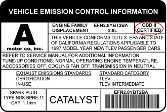 obd_sticker
OBD-II Compliance Sticker: Verify your vehicle is OBD-II certified by locating this sticker under the hood, ensuring compatibility with the OBD2 TTL Adapter.
Supported Vehicle Protocols:
The OBD2 TTL Adapter supports a wide array of vehicle communication protocols, ensuring compatibility with a broad spectrum of vehicles:
- CAN 500Kbps/29bit
- CAN 500Kbps/11bit
- CAN 250Kbps/29bit
- CAN 250Kbps/11bit
- KWP2000 Fast
- KWP2000 5Kbps
Connector Details and Arduino Integration
The adapter is designed for a permanent plug-in to the OBD port in your vehicle. A robust, unpluggable cable extends from the adapter, terminating in a combination of connectors for power and data interfacing. These connectors are designed for direct and easy connection to Arduino boards and breakout shields, ensuring a clean and integrated setup within your car.
Power Connector (2-pin 2.54 Dupont)
- Red: VCC (Connect to Arduino’s VCC pin for power supply)
- Black: GND (Connect to Arduino’s GND pin for ground)
Serial UART Data Connector (2-pin 2.54 Dupont)
- White: Rx (Connect to Arduino’s serial Tx pin for receiving data from Arduino)
- Green: Tx (Connect to Arduino’s serial Rx pin for transmitting data to Arduino)
Important Note for Arduino UNO/Nano: Arduino UNO and Nano utilize a single hardware serial port which is shared with the USB serial connection. When using the adapter with hardware serial, it’s advisable to avoid using serial output in your Arduino code to prevent conflicts. Arduino Leonardo, Mega, and Due, with their multiple hardware serial ports, do not have this limitation.
USB Port (Micro USB)
- For direct connection to a computer or tablet using a micro USB cable.
- Provides a 5V/2A power output, useful for powering external devices or for adapter configuration.
Extended AT Command Set for Advanced Control
Beyond the standard ELM327 command set, the OBD2 TTL Adapter features an extended AT command set, unlocking advanced functionalities:
Motion Sensor Access Commands
- ATACL: Retrieve accelerometer data in G-force units (X, Y, Z axes).
- ATGYRO: Access gyroscope data in degrees per second (X, Y, Z axes).
- ATMAG: Read magnetometer data in milli-Gauss (X, Y, Z axes).
- ATTEMP: Get raw temperature data from the motion sensor.
Quaternion Control and Orientation Commands
- ATQU0/ATQU1: Disable or enable the 9-DOF sensor fusion algorithm (disabled by default upon startup).
- ATORI: Retrieve real-time orientation parameters (Roll, Pitch, Yaw) in degrees, calculated by the 9-DOF sensor fusion.
K-Line and ISO9141-2 Communication Commands
- ATSH: Set header bytes for K-Line and ISO9141-2 communication protocols. Example:
ATSH C1 33 F1 - ATPTH: Configure initializing pulse time (in hexadecimal, 0-255ms range). Example:
ATPTH 19(sets pulse time to 25ms). - ATPTA: Set negative pulse duration before the first data byte (in hexadecimal, 0-255ms range). Example:
ATPTA 32(sets duration to 50ms).
CAN Bus Specific Commands (CAN Bus Sniffing)
- ATSH (11-bit CAN): Set CAN message header for 11-bit CAN bus. Example:
ATSH 7DF - ATSH (29-bit CAN): Set the lower 24 bits of the CAN message header for 29-bit CAN bus. The higher 5 bits are set by the ATCP command. Example:
ATSH DB 33 F1 - ATCP (29-bit CAN): Set CAN priority/higher 5 bits of the header for 29-bit CAN bus. Example:
ATCP 18 - ATCF
or ATCF Set CAN message header filter for CAN sniffing, for 11-bit and 29-bit CAN respectively. Example:: ATCF 7E8 - ATCM : Set CAN message filtering bit mask (32-bit). Example:
ATCM FFFFFFFE(ignores the lowest bit during header filter comparison). - ATM1: Start CAN bus sniffing mode.
- ATM0: Stop CAN bus sniffing mode.
CAN Bus Sniffing Examples:
Typical sniffing on 11-bit 500kbps CAN bus:
1. ATSP6
2. ATCF 700
3. ATCM FFFFFF00
4. ATM1
Typical sniffing on 29-bit 500kbps CAN bus:
1. ATSP7
2. ATCF 18DBF133
3. ATCM FF000000
4. ATM1
Arduino Library: Simplifying Vehicle Data Access
A dedicated and user-friendly Arduino library is provided to facilitate effortless access to all adapter features with any Arduino board. While not every AT command is directly encapsulated in the API, commonly used functionalities are readily available through intuitive functions.
Commonly Used Arduino Library APIs:
setBaudRate(): Configure the adapter’s serial baud rate.readPID(PID, value): Read a specified OBD-II PID and return the parsed value.clearDTC(): Clear diagnostic trouble codes stored in the vehicle’s ECU.getVoltage(): Measure the car battery voltage.getVIN(): Retrieve the Vehicle Identification Number (VIN).getTemperature(): Get the adapter’s internal temperature.readAccel(x, y, z): Read accelerometer X, Y, and Z axis values.memsInit(): Initialize the motion sensor.memsRead(): Read raw motion sensor data.memsOrientation(roll, pitch, yaw): Retrieve computed orientation data (Roll, Pitch, Yaw).
Example Arduino Code: Engine RPM Indicator
This simple example demonstrates how to create an engine RPM indicator using the built-in LED on pin 13 of your Arduino board. The LED will illuminate when the engine RPM exceeds 3000.
#include <obd2uart.h>

COBD obd;

void setup() {
  // Set the debug LED as output
  pinMode(13, OUTPUT);
  // Start serial communication
  obd.begin();
  // Initiate OBD-II connection until success
  while (!obd.init());
}

void loop() {
  int value;
  // Save engine RPM in variable 'value', return true on success
  if (obd.readPID(PID_RPM, value)) {
    // Light up LED on Arduino board when RPM exceeds 3000
    digitalWrite(13, value > 3000 ? HIGH : LOW);
  }
}
Explore more example sketches and advanced applications within the Arduino library examples directory.
Commonly Used PIDs (Predefined in OBD Library):
Engine Related PIDs:
PID_RPM: Engine RPM (revolutions per minute)PID_ENGINE_LOAD: Calculated engine load (percentage)PID_COOLANT_TEMP: Engine coolant temperature (degrees Celsius)PID_ABSOLUTE_ENGINE_LOAD: Absolute engine load (percentage)PID_TIMING_ADVANCE: Ignition timing advance (degrees)PID_ENGINE_OIL_TEMP: Engine oil temperature (degrees Celsius)PID_ENGINE_TORQUE_PERCENTAGE: Engine torque percentage (percentage)PID_ENGINE_REF_TORQUE: Engine reference torque (Newton meters)
Intake/Exhaust Related PIDs:
PID_INTAKE_TEMP: Intake air temperature (degrees Celsius)PID_INTAKE_PRESSURE: Intake manifold absolute pressure (kilopascals)PID_MAF_FLOW: Mass Air Flow sensor reading (grams per second)PID_BAROMETRIC: Barometric pressure (kilopascals)
Speed/Time Related PIDs:
PID_SPEED: Vehicle speed (kilometers per hour)PID_RUNTIME: Engine running time since start (seconds)PID_DISTANCE: Vehicle running distance since codes cleared (kilometers)
Driver Input Related PIDs:
PID_THROTTLE: Throttle position (percentage)PID_AMBIENT_TEMP: Ambient air temperature (degrees Celsius)
Electric Systems Related PIDs:
PID_CONTROL_MODULE_VOLTAGE: Vehicle control module voltage (Volts)PID_HYBRID_BATTERY_PERCENTAGE: Hybrid battery pack remaining life (percentage)
You can extend the PID definitions to access the full range of OBD-II PIDs supported by your vehicle’s ECU.
Comparison of Freematics OBD-II UART Adapter Models
| Features | OBD-II UART Adapter V1 | OBD-II UART Adapter V2 | OBD-II UART Adapter V2.1 |
|---|---|---|---|
| Connection Cable | Fixed | Fixed | Unpluggable |
| Additional Interface | N/A | micro USB | micro USB |
| Motion Sensor | N/A | 6-DOF MPU-6050 | 9-DOF MPU-9250 |
| Voltmeter | Yes | Yes | Yes |
| Max. Output Power | 2A | 2.1A | 2.1A |
| Standby Mode Power | 5mA | 6mA | 6mA |
Frequently Asked Questions (FAQ)
Q: What are the primary applications of the OBD2 TTL Adapter?
A: The most common application is to enable Arduino to easily interface with and access vehicle data. This capability, combined with data from GPS or other sensors, makes it ideal for creating open-source vehicle data loggers and various interactive automotive applications.
Q: How is the adapter powered?
A: The adapter draws power directly from the 12V DC supply available at the vehicle’s OBD-II port.
Q: Does my Arduino require a separate power source when using the adapter?
A: No. The OBD2 TTL Adapter provides a regulated 5V output specifically designed to power Arduino and other connected devices, eliminating the need for an external power supply for your microcontroller.
Q: Do I need a CAN bus shield to use this adapter?
A: Absolutely not. The adapter itself handles the complexities of CAN bus communication. It retrieves data from the CAN bus and converts it into a simpler serial UART interface, which is easily accessible by Arduino and most embedded systems through the provided data connector (Rx and Tx).
Q: How do I physically connect the adapter to my Arduino?
A: The adapter is compatible with all Arduino models. Connection is straightforward: connect the adapter’s Tx pin to Arduino’s Rx (D0) and the adapter’s Rx pin to Arduino’s Tx (D1). For easier and more reliable connections, consider using an I/O breakout shield or an Arduino board with dedicated breakout pins for Rx/Tx/VCC/GND.
Q: Is the power supply from the adapter always on when plugged into the OBD-II port?
A: This depends on your vehicle’s OBD-II port power behavior after the ignition is turned off. In many modern cars, the OBD-II port remains powered even after the ignition is off.
Q: What is the maximum data polling frequency achievable with the adapter?
A: The polling frequency for OBD-II PIDs depends on the speed and load of the vehicle’s ECU. In typical modern cars with CAN bus systems, polling times can be as low as 10ms, potentially allowing up to 100 data polls per second.
Q: What support is available for Arduino programming questions?
A: We focus on providing hardware and adapter-specific support. For Arduino programming assistance, numerous online resources, guides, and tutorials are readily available.
Q: What is the difference between product version and firmware version mentioned?
A: Freematics OBD-II UART Adapter V2.1 is the latest hardware product version and utilizes firmware versioned 1.1. The earlier Freematics OBD-II UART Adapter V1 used firmware version 1.0. This product version refers to the hardware iteration, while firmware version refers to the software running on the adapter.