The dreaded Check Engine Light (CEL) – that little illuminated icon on your Integra’s dashboard that can trigger instant anxiety. While it might seem alarming, the CEL is actually your car’s way of communicating that something needs attention. Fortunately, modern vehicles like the Honda Integra are equipped with sophisticated onboard diagnostic systems, primarily OBD2, to help pinpoint these issues. Understanding Integra Obd2 Codes is the first step in diagnosing and resolving car problems, potentially saving you time and money on unnecessary repairs. This guide will walk you through how to read these codes and what they mean specifically for your Integra.
Understanding OBD2 Systems in Your Integra
OBD2, or On-Board Diagnostics II, is a standardized system implemented in most cars manufactured from 1996 onwards, including the Honda Integra. This system monitors various aspects of your vehicle’s performance and emissions, and when it detects a problem, it illuminates the CEL and stores a corresponding Diagnostic Trouble Code (DTC). These DTCs are crucial for mechanics and car owners alike, providing a starting point for diagnosing issues ranging from minor sensor malfunctions to more significant mechanical problems. For Integra owners, understanding OBD2 codes is particularly useful, whether you’re a seasoned DIYer or simply want to be informed before visiting a mechanic.
Reading Integra OBD2 Codes: Two Methods
There are primarily two ways to retrieve these valuable OBD2 codes from your Integra, depending on the year model and the tools you have available.
Method 1: The Paperclip Method (For Pre-OBD2 Integras)
For older Integra models, particularly those predating the widespread adoption of OBD2 (generally pre-1996), you can use a method often referred to as the “paperclip method” to read engine codes. This technique involves using a paperclip or a piece of wire to jump a specific connector under the dashboard and then interpreting the CEL flashes.
Here’s how to do it:
-
Locate the Service Connector: On the passenger side of your Integra, beneath the glove box and under the dash, look for a green cover. Behind this cover, you’ll find a blue, two-wire connector. This is your service connector.
-
Prepare to Jump the Connector: Turn off the ignition completely. Take a paperclip or a short piece of wire and bend it into a U-shape. This will be used to connect the two terminals within the blue connector.
-
Jump the Connector: Carefully insert one end of the paperclip or wire into one prong of the blue connector and the other end into the second prong. Ensure you are connecting the two wires within the connector.
-
Turn Ignition to “ON”: Turn the ignition key to the “IGN” (Ignition ON) position. Do not start the engine.
-
Observe the CEL Flashes: Watch the Check Engine Light on your dashboard. It will begin to flash in a sequence of long and short flashes.
-
Interpret the Flashes: Integra ECU codes using this method are two-digit codes.
- Long Flashes: Each long flash represents the tens digit of the code.
- Short Flashes: Each short flash represents the ones digit.
- Pause: A longer pause separates the digits of a code, and a longer pause separates different codes if multiple codes are stored.
Example: If you see “LONG-LONG-LONG-SHORT-SHORT-SHORT-SHORT-PAUSE”, this translates to code 34 (three long flashes for ‘3’, four short flashes for ‘4’).
-
Multiple Codes: If your Integra has multiple error codes, they will be displayed sequentially, each separated by a long pause, and then the entire sequence will repeat until you turn the ignition off.
Alt text: Location of the blue service connector under the Integra dashboard for reading check engine light codes using the paperclip method.
While this method can be useful for older Integras, it is less precise than using an OBD2 scanner and only provides basic ECU codes.
Method 2: Using an OBD2 Scanner (For 1996+ Integras)
For 1996 and newer Honda Integras, the most efficient and accurate way to read OBD2 codes is by using an OBD2 scanner. These scanners are readily available online and in auto parts stores, ranging from basic code readers to more advanced diagnostic tools.
Steps to use an OBD2 Scanner:
-
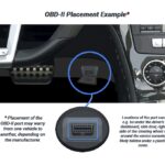
Locate the OBD2 Port: The OBD2 port in your Integra is typically located under the dashboard on the driver’s side. It’s usually near the steering column or in the footwell area. It is a 16-pin trapezoidal connector.
-
Plug in the Scanner: With the ignition off, plug your OBD2 scanner into the OBD2 port. Ensure it’s firmly connected.
-
Turn Ignition to “ON”: Turn the ignition key to the “ON” position. Some scanners might require the engine to be running, but for most code reading, the “ON” position is sufficient.
-
Power On the Scanner: Turn on your OBD2 scanner. It may power on automatically once plugged in or require you to press a power button.
-
Read the Codes: Follow the scanner’s instructions to read DTCs. Typically, you’ll navigate through the scanner’s menu to find options like “Read Codes,” “Diagnostic Codes,” or similar.
-
Understand OBD2 Code Format: OBD2 codes are alphanumeric, starting with a letter followed by four digits (e.g., P0137). The letter indicates the system:
- P: Powertrain (Engine, Transmission)
- B: Body (Body control modules)
- C: Chassis (Brakes, Suspension)
- U: Network/Communication (Communication bus)
The digits provide further specificity about the fault.
-
Record the Codes: Note down all the codes displayed by the scanner. Many scanners can also provide a brief description of the code, which can be helpful.
Alt text: An OBD2 scanner tool plugged into the OBD2 port of a Honda Integra, ready to read diagnostic trouble codes.
Using an OBD2 scanner provides more detailed information than the flashing light method. For instance, a flashing light code 63 (Secondary O2 sensor) might translate into more specific OBD2 codes like P0137 (Secondary Heated Oxygen Sensor Circuit Low Voltage), P0138 (Secondary Heated Oxygen Sensor Circuit High Voltage), or P0139 (Secondary Heated Oxygen Sensor Slow Response). This specificity is invaluable for accurate diagnosis.
Integra OBD2 Codes List: Decoding the Check Engine Light
Once you have retrieved the codes from your Integra, the next step is to understand what they mean. Below is a comprehensive list of ECU codes (for the flashing method) and OBD2 P-codes relevant to Honda Integras.
ECU Codes (Flashing Light Codes)
These two-digit codes are primarily relevant for older Integra models and systems.
- 1: O2A – Oxygen sensor #1
- 2: O2B – Oxygen sensor #2
- 3: MAP – Manifold Absolute Pressure sensor
- 4: CKP – Crank Position Sensor
- 5: MAP – Manifold Absolute Pressure sensor
- 6: ECT – Engine Coolant Temperature sensor
- 7: TPS – Throttle Position Sensor
- 8: TDC – Top Dead Center sensor
- 9: CYP – Cylinder sensor
- 10: IAT – Intake Air Temperature sensor
- 12: EGR – Exhaust Gas Recirculation lift valve
- 13: BARO – Atmospheric Pressure sensor
- 14: IAC (EACV) – Idle Air Control Valve
- 15: Ignition output signal
- 16: Fuel injectors
- 17: VSS – Vehicle Speed Sensor
- 19: Automatic transmission lockup control valve
- 20: Electrical Load Detector
- 21: VTEC spool solenoid valve
- 22: VTEC pressure valve
- 23: Knock sensor
- 30: Automatic transmission A signal
- 31: Automatic transmission B signal
- 36: Traction control (JDM ECUs)
- 41: Primary oxygen sensor heater
- 43: Fuel supply system
- 45: Fuel system too rich or lean
- 48: LAF – Lean Air Fuel sensor
- 54: CKF – Crank Fluctuation Sensor
- 58: TDC sensor #2
- 61: Primary oxygen sensor
- 63: Secondary oxygen sensor
- 65: Secondary oxygen sensor heater
- 67: Catalyst low efficiency (P0420)
- 70: Automatic Transmission Malfunction w/AT Controls
- 71: Random misfire cylinder 1
- 72: Random misfire cylinder 2
- 73: Random misfire cylinder 3
- 74: Random misfire cylinder 4
- 80: Exhaust Gas Recirculation insufficient flow detected
- 86: ECT Sensor (Engine Coolant Temperature) circuit range / performance problem
- 90: Evaporative Emission Control System leak detected in the fuel tank area
- 91: Evaporative Emission Control System insufficient purge flow
OBD2 P-Codes for Integra (1996+ Models)
These P-codes are the standard OBD2 codes and provide more detailed diagnostics for 1996 and newer Integras. This is an extensive list, covering a wide range of potential issues.
- P0010: Variable Valve Timing Control (VTC) Oil Control Solenoid Valve Malfunction
- P0011: Variable Valve Timing Control (VTC) System Malfunction
- P0101: Mass Airflow (MAF) Sensor Range/Performance Problem
- P0102: Mass Airflow (MAF) Sensor Circuit Low Voltage
- P0103: Mass Airflow (MAF) Sensor Circuit High Voltage
- P0106: Manifold Absolute Pressure (MAP) Sensor Range/Performance Problem
- P0107: Manifold Absolute Pressure (MAP) Sensor Circuit Low Voltage
- P0108: Manifold Absolute Pressure (MAP) Sensor Circuit High Voltage
- P0111: Intake Air Temperature (IAT) Sensor Circuit Range/Performance Problem
- P0112: Intake Air Temperature (IAT) Sensor Circuit Low Voltage
- P0113: Intake Air Temperature (IAT) Sensor Circuit High Voltage
- P0116: Engine Coolant Temperature (ECT) Sensor Circuit Range/Performance Problem
- P0117: Engine Coolant Temperature (ECT) Sensor Circuit Low Input
- P0118: Engine Coolant Temperature (ECT) Sensor Circuit High Input
- P0122: Throttle Position (TP) Sensor Circuit Low Input
- P0123: Throttle Position (TP) Sensor Circuit High Input
- P0125: Engine Coolant Temperature (ECT) Sensor Slow Response
- P0128: Cooling System Malfunction
- P0131: Primary Heated Oxygen Sensor (Primary HO2S) (Sensor 1) Circuit Low Voltage
- P0132: Primary Heated Oxygen Sensor (Primary HO2S) (Sensor 1) Circuit High Voltage
- P0133: Rear Air/Fuel Ratio (A/F) Sensor (Bank 1, Sensor 1) Circuit Slow Response
- P0134: Air/Fuel Ratio (A/F) Sensor (Sensor 1) No Activity Detected
- P0135: Primary Heated Oxygen Sensor (Primary HO2S) (Sensor 1) Heater Circuit Malfunction
- P0137: Secondary Heated Oxygen Sensor (Secondary HO2S) Circuit Low Voltage
- P0138: Secondary Heated Oxygen Sensor (Secondary HO2S) Circuit High Voltage
- P0139: Secondary Heated Oxygen Sensor (Secondary HO2S) Slow Response
- P0141: Secondary Heated Oxygen Sensor (Secondary HO2S) (Sensor 2) Heater Circuit Malfunction
- P0143: Third Heated Oxygen Sensor (Third HO2S) (Sensor 3) Circuit Low Voltage
- P0144: Third Heated Oxygen Sensor (Third HO2S) (Sensor 3) Circuit High Voltage
- P0145: Third Heated Oxygen Sensor (Third HO2S) (Sensor 3) Circuit Slow Response
- P0147: Third Heated Oxygen Sensor (Third HO2S) (Sensor 3) Heater Circuit Malfunction
- P0153: Front Air/Fuel Ratio (A/F) Sensor (Bank 2, Sensor 1) Circuit Slow Response
- P0154: Front Air/Fuel Ratio (A/F) Sensor (Bank 2, Sensor 1) Heater System Malfunction
- P0155: Front Air/Fuel Ratio (A/F) Sensor (Bank 2, Sensor 1) Heater Circuit Malfunction
- P0157: Front Secondary Heated Oxygen Sensor (Secondary HO2S) (Bank 2, Sensor 2) Circuit Low Voltage
- P0158: Front Secondary Heated Oxygen Sensor (Secondary HO2S) (Bank 2, Sensor 2) Circuit High Voltage
- P0159: Front Secondary Heated Oxygen Sensor (Secondary HO2S) (Bank 2, Sensor 2) Circuit Slow Response
- P0161: Front Secondary Heated Oxygen Sensor (Secondary HO2S) (Bank 2, Sensor 2) Heater Circuit Malfunction
- P0171: Fuel System Too Lean
- P0172: Fuel System Too Rich
- P0174: Front Bank (Bank 2) Fuel System Too Lean
- P0175: Front Bank (Bank 2) Fuel System Too Rich
- P0191: Fuel Pressure Sensor Range/Performance Problem
- P0192: Fuel Pressure Sensor Circuit Low Voltage
- P0193: Fuel Pressure Sensor Circuit High Voltage
- P0196: EOT Sensor/Range Performance Problem
- P0197: EOT Sensor Circuit Low Voltage
- P0198: EOT Sensor Circuit High Voltage
- P0222: Throttle Position (TP) Sensor 2 Circuit Low Voltage
- P0223: Throttle Position (TP) Sensor 2 Circuit High Voltage
- P0300: Random Misfire
- P0301: No. 1 Cylinder Misfire
- P0302: No. 2 Cylinder Misfire
- P0303: No. 3 Cylinder Misfire
- P0304: No. 4 Cylinder Misfire
- P0305: No. 5 Cylinder Misfire
- P0306: No. 6 Cylinder Misfire
- P0325: Knock Sensor Circuit Malfunction
- P0335: Crankshaft Position (CKP) Sensor Circuit No Signal
- P0336 P0339: Crankshaft Position (CKP) Sensor Circuit Intermittent Interruption
- P0340: Camshaft Position (CMP) Sensor No Signal
- P0341: Camshaft Position (CMP) Sensor A Intermittent Interruption
- P0341: Variable Valve Timing Control (VTC) Phase Gap
- P0344: Camshaft Position (CMP) Sensor Intermittent Interruption
- P0365: Camshaft Position (CMP) Sensor B No Signal
- P0366 P0369: Camshaft Position (CMP) Sensor B Intermittent Interruption
- P0385: Crankshaft Position (CKP) Sensor B No Signal
- P0389: Crankshaft Position (CKP) Sensor B Intermittent Interruption
- P0401: Exhaust Gas Recirculation (EGR) Insufficient Flow
- P0404: Exhaust Gas Recirculation (EGR) Control Circuit Range/Performance Problem
- P0406: Exhaust Gas Recirculation (EGR) Valve Position Sensor Circuit High Voltage
- P0410: Air Pump Circuit Malfunction
- P0411: Secondary Air Injection System Incorrect Flow
- P0420: Catalyst System Efficiency Below Threshold
- P0430: Front Bank Catalyst System Efficiency Below Threshold (Bank 2)
- P0441: Evaporative Emission (EVAP) Control System Incorrect Purge Flow
- P0442: Evaporative Emission (EVAP) System Small Leak Detected
- P0443: Evaporative Emission (EVAP) Canister Purge Valve Circuit Malfunction
- P0451: Fuel Tank Pressure (FTP) Sensor Range/Performance Problem
- P0452: Fuel Tank Pressure (FTP) Sensor Circuit Low Voltage
- P0453: Fuel Tank Pressure (FTP) Sensor Circuit High Voltage
- P0456: Evaporative Emission (EVAP) System Very Small Leak Detected
- P0457: Evaporative Emission (EVAP) System Leak Detected Fuel Fill Cap Loose/Off
- P0461: Fuel Gauge Sending Unit Range/Performance Problem
- P0462: Fuel Gauge Sending Unit Circuit Low Voltage
- P0463: Fuel Gauge Sending Unit Circuit High Voltage
- P0496: Evaporative Emission (EVAP) System High Purge Flow
- P0497: Evaporative Emission (EVAP) System Low Purge Flow
- P0498: Evaporative Emission (EVAP) Canister Vent Shut Valve Control Circuit Low Voltage
- P0499: Evaporative Emission (EVAP) Canister Vent Shut Valve Control Circuit High Voltage
- P0500: Vehicle Speed Sensor (VSS) Circuit Malfunction
- P0501: Vehicle Speed Sensor (VSS) Range/Peformance Problem
- P0505: Idle Control System Malfunction
- P0506: Idle Control System RPM Lower Than Expected
- P0507: Idle Control System RPM Higher Than Expected
- P0511: Idle Air Control (IAC) Valve Circuit Malfunction
- P0521: EOP Sensor Range/Performance Problem
- P0522: EOP Sensor Circuit Low Voltage
- P0523: EOP Sensor Circuit High Voltage
- P0560: ECM Back-up Circuit Low Voltage
- P0563: Engine Control Module (ECM)/Powertrain Control Module (PCM) Power Source Circuit Unexpected Voltage
- P0600: Multiplex Control System Troubleshooting
- P0603: ECM/PCM Internal Control Module Keep Alive Memory (KAM) Error
- P0606: ECM/PCM Processor Malfunction
- P0661: Intake Manifold Runner Control (IMRC) Valve Position Sensor Circuit Low Voltage
- P0662: Intake Manifold Runner Control (IMRC) Valve Position Sensor Circuit High Voltage
- P0685: ECM/PCM Power Relay Control Circuit Malfunction
- P0700: Automatic Transmission Control System
- P0705: Short in Transmission Range Switch Circuit (Multiple Shift-position Input)
- P0706: Open in Transmission Range Switch Circuit
- P0710 P0711: Problem in ATF Temperature Sensor Circuit
- P0712: Short in ATF Temperature Sensor Circuit
- P0713: Open in ATF Temperature Sensor Circuit
- P0715 P0716: Problem in Mainshaft Speed Sensor Circuit
- P0717: Problem in Mainshaft Speed Sensor Circuit (No Signal Input)
- P0718: Mainshaft Speed Sensor Intermittent Failure
- P0720: Countershaft Speed Sensor Circuit Malfunction
- P0720 P0721: Problem in Countershaft Speed Sensor Circuit
- P0722: Problem in Countershaft Speed Sensor Circuit (No Signal Input)
- P0723: Countershaft Speed Sensor Intermittent Failure
- P0725: Engine Speed Input Circuit Malfunction
- P0730: Problem in Shift Control System
- P0731: Problem in 1st Clutch and 1st Clutch Hydraulic Circuit
- P0732: Problem in 2nd Clutch and 2nd Clutch Hydraulic Circuit
- P0733: Problem in 3rd Clutch and 3rd Clutch Hydraulic Circuit
- P0734: Problem in 4th Clutch and 4th Clutch Hydraulic Clutch
- P0735: Problem in 5th Clutch and 5th Clutch Hydraulic Circuit
- P0740: Problem in Lock-up Control System
- P0741: Torque Converter Clutch Hydraulic Clutch Stuck OFF
- P0743: Problem in Torque Converter Clutch Solenoid Valve Circuit
- P0745: Problem in Hydraulic Control System of A/T Clutch Pressure Control Solenoid Valve A Circuit
- P0746: A/T Clutch Pressure Control Solenoid Valve A Stuck OFF
- P0747: A/T Clutch Pressure Control Solenoid Valve A Stuck ON
- P0748: Problem in A/T Clutch Pressure Control Solenoid Valve A Circuit
- P0750: Problem in Hydraulic Control System of Shift Solenoid Valve A Circuit
- P0751: Shift Solenoid Valve A Stuck OFF
- P0752: Shift Solenoid Valve A Stuck ON
- P0753: Problem in Shift Solenoid Valve A Circuit
- P0756: Shift Solenoid Valve B Stuck OFF
- P0757: Shift Solenoid Valve B Stuck ON
- P0758: Problem in Shift Solenoid Valve B Circuit
- P0761: Shift Solenoid Valve C Stuck OFF
- P0762: Shift Solenoid Valve C Stuck ON
- P0763: Problem in Shift Solenoid Valve C Circuit
- P0771: Shift Solenoid Valve E Stuck OFF
- P0773: Problem in Shift Solenoid Valve E Circuit
- P0775: Problem in the Hydraulic Control System of A/T Clutch Pressure Control Solenoid Valve B Circuit
- P0776: A/T Clutch Pressure Control Solenoid Valve B Stuck OFF
- P0777: A/T Clutch Pressure Control Solenoid Valve B Stuck ON
- P0778: Problem in A/T Clutch Pressure Control Solenoid Valve B Circuit
- P0780: Problem in Shift Control System
- P0795: Problem in Hydraulic Control System of A/T Clutch Pressure Control Solenoid Valve C Circuit
- P0796: A/T Clutch Pressure Control Solenoid Valve C Stuck OFF
- P0797: A/T Clutch Pressure Control Solenoid Valve C Stuck ON
- P0798: Problem in A/T Clutch Pressure Control Solenoid Valve C Ciruit
- P0812: Open in Transmission Range Switch ATP RVS Switch Circuit
- P0842: Short in 2nd Clutch Transmission Fluid Pressure Switch Clutch, or 2nd Clutch Transmission Fluid Pressure Switch (Clutch) Stuck ON
- P0843: Open in 2nd Clutch Transmission Fluid Pressure Switch Circuit, or 2nd Clutch Transmission Fluid Pressure Switch Stuck OFF
- P0845: Problem in 3rd Clutch Pressure Switch Circuit
- P0847: Short in 3rd Clutch Transmission Fluid Pressure Switch Circuit, or 3rd Clutch Transmission Fluid Pressure Switch Stuck ON
- P0848: Open in 3rd Clutch Transmission Fluid Pressure Switch Circuit, or 3rd Clutch Transmission Fluid Pressure Switch Stuck OFF
- P0872: Short in 4th Clutch Transmission Fluid Pressure Switch Circuit, or 4th Clutch Transmission Fluid Pressure Switch Stuck ON
- P0873: Open in 4th Clutch Transmission Fluid Pressure Switch Circuit, or 4th Clutch Transmission Fluid Pressure Switch Stuck OFF
- P0962: Problem in A/T Clutch Pressure Control Solenoid Valve A Circuit
- P0963: Problem in A/T Clutch Pressure Control Solenoid Valve A
- P0966: Problem in A/T Clutch Pressure Control Solenoid Valve B Circuit
- P0967: Problem in A/T Clutch Pressure Control Solenoid Valve B
- P0970: Problem in A/T Clutch Pressure Control Solenoid Valve C Circuit
- P0971: Problem in A/T Clutch Pressure Control Solenoid Valve C
- P0973: Short in Shift Solenoid Valve A Circuit
- P0974: Open in Shift Solenoid Valve A Circuit
- P0976: Short in Shift Solenoid Valve B Circuit
- P0977: Open in Shift Solenoid Valve B Circuit
- P0979: Short in Shift Solenoid Valve C Circuit
- P0980: Open in Shift Solenoid Valve C Circuit
- P0982: Short in Shift Solenoid Valve D Circuit
- P0983: Open in Shift Solenoid Valve D Circuit
- P0985: Short in Shift Solenoid Valve E Circuit
- P0986: Open in Shift Solenoid Valve E Circuit
- P1020: Valve Pause System Stuck Off
- P1021: Valve Pause System Stuck On
- P1025: Valve Pause System Sticking Off
- P1026: Valve Pause System Sticking On
- P1077: Intake Manifold Runner Control (IMRC) System Malfunction (Low rpm)
- P1078: Intake Mainfold Runner Control (IMRC) System Malfunction (High rpm)
- P1106: Barometric Pressure (BARO) Sensor Circuit Range/Performance Problem
- P1107: Barometric Pressure (BARO) Sensor Circuit Low Voltage
- P1108: Barometric Pressure (BARO) Sensor Circuit High Voltage
- P1121: Throttle Position (TP) Sensor Lower Than Expected
- P1122: Throttle Position (TP) Sensor Higher Than Expected
- P1128: Manifold Absolute Pressure (MAP) Sensor Circuit Lower Than Expected
- P1129: Manifold Absolute Pressure (MAP) Sensor Circuit Higher Than Expected
- P1130: Demand for Changing Both Secondary Heated Oxygen Sensor (Secondary HO2S) (Sensor 2) and Third Heated Oxygen Sensor (Third HO2S) (Sensor 3)
- P1149: Air/Fuel Ratio (A/F) Sensor (Sensor 1) Range/Performance Problem
- P1149: Air/Fuel Ratio Sensor (Sensor 1) Circuit Lean Range
- P1157: Air/Fuel Ratio (A/F) Sensor (Sensor 1) AFS Line High Voltage
- P1157: Air/Fuel Ratio (A/F) Sensor (Sensor 1) Circuit High Voltage
- P1157: Air/Fuel Ratio (A/F) Sensor (Sensor 1) Range/Performance Problem
- P1158: Air/Fuel Ratio (A/F) Sensor (Sensor 1) AFS- Terminal Low Voltage
- P1159: Air/Fuel Ratio (A/F) Sensor (Sensor 1) AFS+ Terminal Low Voltage
- P1162: Air/Fuel Ratio (A/F) Sensor (Sensor 1) Slow Response
- P1163: Air/Fuel Ratio (A/F) Sensor (Sensor 1) Slow Response
- P1163: Air/Fuel Ratio Sensor (Sensor 1) Slow Response
- P1164: Air/Fuel Ratio (A/F) Sensor (Sensor 1) Range/Performance Problem
- P1164: Air/Fuel Ratio (AF) Sensor (Sensor 1) Circuit Range/Performance
- P1165: Air/Fuel Ratio (A/F) Sensor (Sensor 1) Range/Performance Problem
- P1165: Air/Fuel Ratio Sensor (Sensor 1) Circuit Range/Performance
- P1166: Air/Fuel Ratio (A/F) Sensor (Sensor 1) Heater System Electrical Problem
- P1166: Heated Oxgen Sensor Sensor1 (Primary HO2S) Heater Circuit Malfunction
- P1167: Air/Fuel Ratio (A/F) Sensor (Sensor 1) Heater System Malfunction
- P1167: Heated Oxygen Sensor Sensor1 (Primary LAF HO2S) Heater System Malfunction
- P1168: Air/Fuel Ratio (A/F) Sensor (Sensor 1) LABEL Low Voltage
- P1169: Air/Fuel Ratio (A/F) Sensor (Sensor 1) LABEL High Voltage
- P1182: Fuel Temperature Sensor Circuit Low Voltage
- P1183: Fuel Temperature Sensor Circuit High Voltage
- P1253 P1259: VTEC System Malfunction
- P1297: Electric Load Detector (ELD) Circuit Low Voltage
- P1298: Electric Load Detector (ELD) Circuit High Voltage
- P1300: Random Misfire
- P1324: Knock Sensor Power Source Circuit Low Voltage
- P1336: Engine Speed (RPM) Fluctuation Sensor Intermittent Interruption
- P1337: Engine Speed (RPM) Fluctuation Sensor No Signal
- P1355: Front Ignition Coil Power Circuit Malfunction
- P1359: Crankshaft Position (CKP)/Top Dead Center (TDC) Sensor Circuit Malfunction
- P1361: Camshaft Position (CMP) Sensor A (Top Dead Center (TDC) Sensor) Intermittent Interruption
- P1361: Top Dead Center (TDC) Sensor Intermittent Interruption
- P1362: Camshaft Position (CMP) Sensor A (Top Dead Center (TDC) Sensor) No Signal
- P1362: Top Dead Center (TDC) Sensor No Signal
- P1366: Camshaft Position (CMP) Sensor B (Top Dead Center (TDC) Sensor) Intermittent Interruption
- P1366: Top Dead Center (TDC) Sensor 2 Intermittent Interruption
- P1367: Camshaft Position (CMP) Sensor B (Top Dead Center (TDC) Sensor) No Signal
- P1367: Top Dear Center (TDC) Sensor 2 No Signal
- P1381: Cylinder Position (CYP) Sensor Intermittent Interruption
- P1382: Cylinder Position (CYP) Sensor No Signal
- P1410: Air Pump Malfunction
- P1415: Air Pump Electric Current Sensor Circuit Low Voltage
- P1416: Air Pump Electric Current Sensor Circuit High Voltage
- P1420: Nox Adsorptive Catalyst System Efficiency Below Threshold
- P1438: Motor Drive Module (MDM) Overheating Signal Circuit
- P1438: Motor Drive Module (MDM) Overheating
- P1439: Motor Drive Module (MDM) Short Circuit Sensor Problem
- P1439: Motor Drive Module (MDM) Short Circuit
- P1440: IMA System Problem
- P1445: Bypass Control Problem
- P1448 P1449: Battery Module Overheating
- P1449: Battery Cell Overheating
- P1449: Battery Module Individual Voltage Input Deviation
- P1449: Battery Module Deterioration
- P1449: Battery Module Deviation
- P1454: Fuel Tank Pressure (FTP) Sensor Range/Performance Problem
- P1456: Evaporative Emissions (EVAP) Control System Leakage (Fuel Tank System)
- P1457: Evaporative Emissions (EVAP) Control System Leakage (EVAP Canister System)
- P1459: Evaporative Emission (EVAP) Purge Flow Switch Malfunction
- P1491: Exhaust Gas Recirculation (EGR) Valve Insufficient Lift
- P1486: Cooling System Malfunction
- P1491: Exhaust Gas Recirculation (EGR) Valve Insufficient Lift
- P1498: Exhaust Gas Recirculation (EGR) Valve Position Sensor Circuit High Voltage
- P1505: Positive Crankcase Ventilation (PCV) Air Leakage
- P1508 P1519: Idle Air Control Valve (IACV) Circuit Malfunction
- P1509: Idle Air Control Valve (IACV) Circuit Failure
- P1522: Brake Booster Pressure Sensor Circuit Low Voltage
- P1523: Brake Booster Pressure Sensor Circuit High Voltage
- P1524: Brake Booster Pressure Sensor Range/Performance Problem
- P1541: Climate Control Unit Signal Circuit Low Voltage
- P1542: Climate Control Unit Signal Circuit High Voltage
- P1565: Motor Commutation Signal Problem
- P1568: Battery Module Individual Voltage Input Problem
- P1568: Battery Module Temperature Signal Circuit Problem
- P1568: Battery Cell Temperature Signal Circuit Problem
- P1572: Motor Drive Module (MDM) Temperature Signal Circuit Low Input
- P1572: Motor Drive Module (MDM) Temperature Signal Circuit High Input
- P1576: Motor Drive Module (MDM) Voltge Signal Circuit Low Input
- P1577: High Voltage Detection Signal Circuit Problem
- P1580: Battery Current Circuit Problem
- P1581: Motor Power Inverter (MPI) Module Current Signal Circuit Low Input
- P1581: Motor Power Inverter (MPI) Module Current Signal Circuit High Input
- P1581: Motor Power Inverter (MPI) Module Current Signal Circuit Problem
- P1582: Motor Current U Phase Signal Circuit Low Input
- P1582: Motor Current U Phase Signal Circuit High Input
- P1583: Motor Current V Phase Signal Circuit Low Input
- P1583: Motor Current V Phase Signal Circuit High Input
- P1584: Motor Current W Phase Signal Circuit Low Input
- P1584: Motor Current W Phase Signal Circuit High Input
- P1585: Motor Current Signal Circuit Problem
- P1586: Motor Power Inverter (MPI) Module Current Signal/Battery Current Signal Circuit Problem
- P1607: Engine Control Module (ECM)/Powertrain Control Module (PCM) Internal Circuit Malfunction
- P1630: Transmission Control Module
- P1635: Battery Condition Monitor (BCM) Module Proble
- P1639: MOTB Signal Circuit Malfunction
- P1640: ACTTRQ Motor Torque Signal Circuit Low Input
- P1641: ACTTRQ Motor Torque Signal Circuit High Input
- P1642: QBATT Battery Signal Circuit Low Input
- P1643: QBATT Battery Signal Circuit High Input
- P1644: MOTFSA Signal Malfunction
- P1645: MOTFSB Signal Malfunction
- P1646: MOTSTB Signal Malfunction
- P1647: Power Command Signal Circuit Low Input
- P1647: Power Command Signal Circuit High Input
- P1647: Engine Torque Signal Circuit Low Input
- P1647: Engine Torque Signal Circuit High Input
- P1647: Mode Signal Circuit 1 Low Input
- P1647: Mode Signal Circuit 1 High Input
- P1647: Mode Signal Circuit 2 Problem
- P1647: Engine Speed Signal Circuit Problem
- P1648: Battery Condition Monitor (BCM) Module Communication Signal Circuit Problem
- P1648: Motor Control Module (MCM) Communication Signal Circuit Problem
- P1655: CVT-FI TMA/TMB Signal Line Failure
- P1656: Problem in PCM-toVTM-4 Control Unit Communications Circuit
- P1660: A/T-FI Data Line Failure/TCM – ECM Halt
- P1676 P1678: FPTDR Signal Line Failure
- P1679: RSCD Signal Circuit Malfunction
- P1681: A/T FI Signal A Cicuit Low Voltage
- P1682: A/T FI Signal A Circuit High Voltage
- P1683: Throttle Valve Default Position Spring Performance Problem
- P1684: Throttle Valve Return Spring Performance Problem
- P1686: A/T FI Signal B Circuit Low Voltage
- P1687: A/T FI Signal B Circuit High Voltage
- P1705: Short in Transmission Range Switch Circuit (More than one range position is on at the same time)
- P1706: Open in Transmission Range Switch Circuit
- P1709: Problem Transmission Gear Selection Switch Circuit
- P1730: Problem in Shift Control System: Shift Solenoid Valve A and D Stuck OFF Shift Solenoid Valve B Stuck ON Shift Valves A, B, and D Stuck
- P1731: Problem in Shift Control System: Shift Solenoid Valve E Stuck ON Shift Valve E Stuck A/T Clutch Pressure Control Solenoid Valve A Stuck OFF
- P1732: Problem in Shift Control System: Shift Solenoid Valve B and C Stuck ON Shift Valves B and C Stuck
- P1733: Problem in Shift Control System: Shift Solenoid Valve D Stuck ON Shift Valve D Stuck A/T Clutch Pressure Control Solenoid Valve C Stuck OFF
- P1734: Problem in Shift Control System: Shift Solenoid Valves B and C Stuck ON Shift Valves B and C Stuck
- P1738: Problem in 2nd Clutch Pressure Switch Circuit
- P1739: Problem in 3rd Clutch Pressure Switch Circuit
- P1740: Problem in 4th Clutch Pressure Switch Circuit
- P1750: Mechanical Problem in Hydraulic Control System of A/T Clutch Pressure Control Solenoid Valve Assemblies A and B, or Problem in the Hydraulic Control System
- P1751: Mechanical Problem in Hydraulic Control System of Shift Solenoid Valve B and A/T Clutch Pressure Control Solenoid Valves A and B, or Problem in the Hydraulic Control System
- P1753: Problem in Torque Converter Clutch Solenoid Valve Circuit
- P1751 P1768: Problem in Torque Converter Clutch Solenoid Valve B Circuit
- P1773: Problem in A/T Clutch Pressure Control Solenoid Valve B Circuit
- P1790: Throttle Position (TP) Sensor Circuit Malfunction
- P1791: Vehicle Speed Sensor (VSS) Range/Performance Problem
- P1792: Problem in Engine Coolant Temperature (ECT) Sensor Circuit
- P1793: Manifold Absolute Pressure Sensor Circuit
- P1870: Problem in CVT Speed Change Control Valve Assembly Circuit
- P1873: Problem in CVT Pulley Pressure Control Valve Assembly Circuit
- P1879: Problem in CVT Start Clutch Pressure Control Valve Assembly Circuit
- P1882: Problem in Inhibitor Solenoid Circuit
- P1884: Secondary Gear Speed Sensor 2 Circuit Malfunction
- P1885: CVT Drive Pulley Speed Sensor Circuit
- P1886: CVT Driven Pulley Speed Sensor Circuit
- P1888: CVT Speed Sensor
- P1889: Problem in CVT Speed Sensor 2 Circuit
- P1890: Shift Control System
- P1891: Problem in Start Clutch System
- P1894: CVT Speed Change Control Valve Circuit
- P1895: CVT Pulley Pressure Control Valve Circuit
- P2101: Throttle Actuator System Malfunction
- P2108: Throttle Actuator Control Module Problem
- P2118: Throttle Actuator Current Range/Performance Problem
- P2122: Accelerator Pedal Position (APP) Sensor 1 (Throttle Position Sensor D) Circuit Low Voltage
- P2123: Accelerator Pedal Position (APP) Sensor 1 (Throttle Position Sensor D) Circuit High Voltage
- P2127: Accelerator Pedal Position (APP) Sensor 2 (Throttle Position Sensor E) Circuit Low Voltage
- P2128: Accelerator Pedal Position (APP) Sensor 2 (Throttle Position Sensor E) Circuit High Voltage
- P2135: Throttle Position (TP) Sensor 1/2 Incorrect Voltage Correlation
- P2138: Accelerator Pedal Position (APP) Sensor 1/2 (Throttle Position Sensor D/E) Incorrect Voltage Correlation
- P2176: Throttle Actuator Control System Idle Position Not Learned
- P2195: Air/Fuel Ratio (A/F) Sensor (Sensor 1) Signal Stuck Lean
- P2197: Front Air/Fuel Ratio (A/F) Sensor (Bank 2, Sensor 1) Signal Stuck Lean
- P2227: Barometric Pressure (BARO) Sensor Circuit Range/Performance Problem
- P2228: Barometric Pressure (BARO) Sensor Circuit Low Voltage
- P2229: Barometric Pressure (BARO) Sensor Circuit High Voltage
- P2237: Rear Air/Fuel Ratio (A/F) Sensor (Bank 1, Sensor 1) IP Line High Voltage
- P2238: Air/Fuel Ratio (A/F) Sensor (Sensor 1) AFS+ Line Low Voltage
- P2238: Rear Air/Fuel Ratio (A/F) Sensor (Bank 1, Sensor 1) IP Line Low Voltage
- P2240: Front Air/Fuel Ratio (A/F) Sensor (Bank 2, Sensor 1) IP Line High Voltage
- P2241: Front Air/Fuel Ratio (A/F) Sensor (Bank 2, Sensor 1) IP Line Low Voltage
- P2243: Rear Air/Fuel Ratio (A/F) Sensor (Bank 1, Sensor 1) VCENT Line High Voltage
- P2245: Rear Air/Fuel Ratio (A/F) Sensor (Bank 1, Sensor 1) VCENT Line Low Voltage
- P2247: Front Air/Fuel Ratio (A/F) Sensor (Bank 2, Sensor 1) VCENT Line High Voltage
- P2249: Front Air/Fuel Ratio (A/F) Sensor (Bank 2, Sensor 1) VCENT Line Low Voltage
- P2251: Rear Air/Fuel Ratio (A/F) Sensor (Bank 1, Sensor 1) VS Line High Voltage
- P2252: Air/Fuel Ratio (A/F) Sensor (Sensor 1) AFS- Line Low Voltage
- P2254: Front Air/Fuel Ratio (A/F) Sensor (Bank 2, Sensor 1) VS Line High Voltage
- P2255: Front Air/Fuel Ratio (A/F) Sensor (Bank 2, Sensor 1) VS Line Low Voltage
- P2279: Intake Air System Leak
- P2413: Exhaust Gas Recirculation (EGR) System Range/Performance Problem
- P2422: Evaporative Emission (EVAP) System Vent Shut Valve Close Malfunction
- P2552: Throttle Actuator Control Module Relay Malfunction
- P2627: Rear Air/Fuel Ratio (A/F) Sensor (Bank 1, Sensor 1) LABEL Circuit Low Voltage
- P2628: Rear Air/Fuel Ratio (A/F) Sensor (Bank 1, Sensor 1) LABEL Circuit High Voltage
- P2630: Front Air/Fuel Ratio (A/F) Sensor (Bank 2, Sensor 1) LABEL Circuit Low Voltage
- P2631: Front Air/Fuel Ratio (A/F) Sensor (Bank 2, Sensor 1) LABEL Circuit High Voltage
- P2646: VTEC Oil Pressure Switch Circuit Low Voltage
- P2647: VTEC Oil Pressure Switch Circuit High Voltage
- P2648: VTEC Solenoid Valve Circuit Low Voltage
- P2649: VTEC Solenoid Valve Circuit High Voltage
- P2769: Short in Torque Converter Clutch Solenoid Valve Circuit
- P2770: Open in Torque Converter Clutch Solenoid Valve Circuit
- P2A00: Air/Fuel Ratio (A/F) Sensor (Sensor 1) Range/Performance Problem
- P2A03: Front A/F Sensor Circuit (Bank 2, Sensor 1) Circuit Range/Performance Problem
- U0073: FCAN Malfunction (Bus-off)
- U0107: Lost Communication With Throttle Actuator Control Module
- U0121: FCAN Malfunction (TCS-PCM)
- U0155: FCAN Malfunction (Gauge Control Module-ECM)
(ABS Codes – 94-97 Integras)
- 1: ABS pump motor over-run
- 2: ABS pump motor
- 3: High pressure leakage
- 4: Pressure switch
- 8: High pressure system
- 21: Parking brake
- 31: Pulser RF
- 32: Pulser LF
- 34: Pulser RR
- 38: Pulser LR
- 312: Different diameter tires
- 41: Wheel sensor RF
- 42: Wheel sensor LF
- 44: Wheel sensor RR
- 48: Wheel sensor LR
- 5: Rear wheel lock – R/L
- 54: Rear wheel lock – R
- 58: Rear wheel lock – L
- 6: Fail-safe relay – F/R
- 61: Fail-safe relay – F
- 64: Fail-safe relay – R
- 71: Solenoid – RF
- 72: Solenoid – LF
- 74: Solenoid – R
- 81: ABS function
- 82: CPU comparison
- 84: IC self-check
(ABS Codes – 98+ Integras)
- 11: Wheel sensor FR (open/short to body ground/short to power)
- 13: Wheel sensor FL (open/short to body ground/short to power)
- 15: Wheel sensor RR (open/short to body ground/short to power)
- 17: Wheel sensor RL (open/short to body ground/short to power)
- 12: Wheel sensor FR (electrical noise/intermittent interruption)
- 14: Wheel sensor FL (electrical noise/intermittent interruption)
- 16: Wheel sensor RR (electrical noise/intermittent interruption)
- 18: Wheel sensor RL (electrical noise/intermittent interruption)
- 21: Pulser FR
- 22: Pulser FL
- 23: Pulser RR
- 24: Pulser RL
- 31: Solenoid FR-IN (short to body ground/short to wire)
- 32: Solenoid FR-OUT (short to body ground/short to wire)
- 33: Solenoid FL-IN (short to body ground/short to wire)
- 34: Solenoid FL-OUT (short to body ground/short to wire)
- 35: Solenoid RR-IN (short to body ground/short to wire)
- 36: Solenoid RR-OUT (short to body ground/short to wire)
- 37: Solenoid RL-IN (short to body ground/short to wire)
- 38: Solenoid RL-OUT (short to body ground/short to wire)
- 41: Wheel lock FR
- 42: Wheel lock FL
- 43: Wheel lock RR
- 44: Wheel lock RL
- 51: Motor lock
- 52: Motor stuck OFF
- 53: Motor stuck ON
- 54: Fail-safe relay
- 61: Ignition voltage
- 62: Ignition voltage
- 71: Different diameter tire
- 81: Central processing unit (CPU)
Conclusion
Understanding and diagnosing Integra OBD2 codes is a valuable skill for any Integra owner. Whether you are using the traditional paperclip method for older models or leveraging the power of a modern OBD2 scanner, knowing how to retrieve and interpret these codes can save you time, money, and stress. By consulting the comprehensive code lists provided, you can take a proactive approach to vehicle maintenance and ensure your Integra continues to run smoothly for years to come. Remember that OBD2 codes provide a starting point for diagnosis. Further investigation and potentially professional mechanic assistance may be required to accurately pinpoint and resolve the root cause of the problem indicated by the codes.