For car enthusiasts and DIY mechanics, accessing your vehicle’s diagnostic data is invaluable. The On-Board Diagnostics II (OBD2) system provides a wealth of information about your car’s health and performance. While there isn’t a direct “OBD2 to USB” wiring method in the traditional sense, you can create a custom harness to connect your OBD2 port to devices that utilize USB interfaces for diagnostics. This guide will walk you through the process of wiring an OBD2 connector, focusing on the essential connections needed for many USB-based OBD2 diagnostic tools.
Understanding OBD2 and Connectivity for USB Devices
It’s important to clarify that you don’t directly wire an OBD2 port to a USB port for data transfer in the same way you connect a USB drive to your computer. Instead, OBD2 communicates using protocols like CAN bus, and USB is a different communication standard. To bridge this gap, OBD2 to USB adapters or cables contain electronics that convert the OBD2 signals into a USB data stream that your computer or other USB-compatible devices can understand.
This guide focuses on creating a basic OBD2 wiring harness that provides the necessary connections for many of these USB OBD2 adapters to function. We will be wiring the essential pins from an OBD2 connector to a separate 4-pin connector, which can then be adapted or used with specific USB-based diagnostic interfaces.
Tools and Parts You’ll Need
Before you begin, gather the necessary tools and parts. Having everything at hand will make the wiring process smoother and more efficient.
- Wire strippers/cutters: For stripping insulation from wires and cutting wires to length.
- Needle-nose pliers: Useful for handling small components and crimping connector pins.
- Molex crimping tool (optional but recommended): For properly crimping pins onto wires, ensuring a secure and reliable connection. If you don’t have one, pliers can be used with extra care.
- Soldering iron (recommended): For creating a more robust electrical connection by soldering wires to pins. While crimping can be sufficient, soldering adds an extra layer of reliability.
- 4-pin connector kit: This will serve as the intermediary connector for your OBD2 harness. Ensure it’s compatible with your wire gauge. (Example Connector)
- OBD-II Cable or Connector with wires: You can either purchase a complete OBD2 cable and cut off the end, or just get a female OBD2 connector and wire it yourself. (Example OBD2 Cable)
If you opt to wire the OBD2 connector from scratch, ensure you have appropriate gauge wire (22-16AWG is suitable for this application) and understand the OBD2 pinout. For this guide, we’re assuming you’re using an OBD2 cable where the internal wires are already connected to the OBD2 connector pins.
Step-by-Step Guide: Wiring Your OBD2 Connector
Let’s get started with the wiring process. Remember to work in a well-lit and organized space.
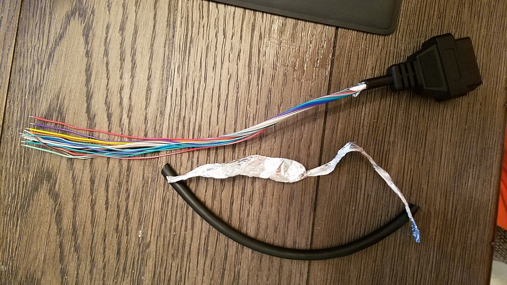
Step 1: Prepare the OBD2 Cable
Begin by preparing your OBD2 cable. Carefully remove the outer sheath and shielding of the OBD2 cable to expose the individual wires inside. Identify the four wires we will be using:
- Pin 4 (Chassis Ground) – Often an orange wire in the example cable.
- Pin 6 (CAN High [J-2284]) – Often a green wire in the example cable.
- Pin 14 (CAN Low [J-2284]) – Often a brown wire with a white stripe in the example cable.
- Pin 16 (Battery Power) – Often a green wire with a white stripe in the example cable.
Isolate these four wires from the rest of the wires in the OBD2 cable. You can neatly bundle and zip-tie the unused wires to keep them out of the way.
Step 2: Preparing the Wires and Pins for the 4-Pin Connector
The wires within the OBD2 cable are often very thin (e.g., 26AWG). The pins for the 4-pin connector kit are typically designed for slightly thicker wires (e.g., 22AWG). To ensure a good connection, we need to prepare the wire ends.
Strip about 3/8 inch of insulation from the end of each of the four selected OBD2 wires. Since the wires might be thin for the connector pins, fold the exposed wire strands over to double their thickness and twist them tightly. This will help them fit more snugly within the connector pins.
Slide a rubber seal (from the 4-pin connector kit) onto each of the four wires. These seals provide environmental protection to the connection.
Step 3: Soldering (or Crimping) the Wires to Pins
Now, we attach the prepared wires to the pins of the 4-pin connector. Each pin has two sets of prongs: one to grip the wire strands and another to grip the rubber seal.
Insert a prepared wire into a connector pin, ensuring the wire strands align with the front set of prongs. The wire from the OBD2 cable might appear small compared to the pin, highlighting why thickening the wire by folding it over is beneficial.
Soldering (Recommended): Soldering provides a strong and electrically sound connection, especially with thin wires. If you choose to solder, apply a small amount of solder to the wire where it meets the pin’s prongs. Ensure the solder flows smoothly and creates a solid joint.
Crimping (Alternative): If you have a crimping tool, use it to crimp the front prongs of the pin securely around the wire. If you don’t have a crimping tool, you can carefully use needle-nose pliers to fold the prongs over the wire. Squeeze the prongs at an angle to gradually fold them over, ensuring they grip the wire tightly. You can further secure the crimp by gently crushing the prongs a bit more with pliers.
Step 4: Assembling the 4-Pin Connector
Slide the rubber seal up the wire until it sits between the rear set of prongs on the connector pin. Use the same crimping or pliers technique to fold these rear prongs over the rubber seal. This secures the seal and provides strain relief for the wire.
Repeat steps 2-4 for the remaining three wires and connector pins.
While not explicitly necessary for basic functionality, some guides recommend twisting pairs of wires together to reduce electromagnetic interference. If you wish to do this, pair and twist the wires as follows:
- Pin 4 (Orange – Ground) / Pin 16 (Green w/white stripe – Power)
- Pin 6 (Green – CAN High) / Pin 14 (Brown w/white stripe – CAN Low)
Finally, insert the completed pins into the 4-pin connector housing in the correct orientation. Refer to the pinout diagram and insert the pins into the corresponding slots:
- Pin 14 (Brown w/white stripe – CAN Low) > Connector Slot A
- Pin 6 (Green – CAN High) > Connector Slot B
- Pin 16 (Green w/white stripe – Power) > Connector Slot C
- Pin 4 (Orange – Ground) > Connector Slot D
Push each pin into the connector housing from the rear until you hear a click, indicating it is locked in place. Using needle-nose pliers can help gently pull the wire from the front to ensure the pin is fully seated and locked.
Step 5: Testing Your OBD2 Harness
Your DIY OBD2 harness is now complete! You can test it by connecting it to your vehicle’s OBD2 port and then to a compatible USB OBD2 diagnostic tool or adapter. Ensure your diagnostic software is properly installed and configured.
Successful testing, such as checking and clearing diagnostic trouble codes, confirms that your wiring is correct and functional.
Important Considerations and Disclaimer
Disclaimer: This guide is for informational purposes and intended for individuals with basic electronics and automotive knowledge. Incorrect wiring can potentially damage your vehicle’s electronics or diagnostic tools. Proceed at your own risk. If you are not comfortable with automotive wiring, it is recommended to consult a professional.
- Pinout Verification: Always double-check the OBD2 pinout and the pinout of your 4-pin connector to ensure correct wiring.
- Quality Components: Using good quality connectors and wire will improve the reliability and longevity of your harness.
- Shielding (Optional): For more demanding applications or environments with potential electromagnetic interference, consider using shielded wire for the CAN bus lines (Pins 6 and 14).
- USB Adapter Compatibility: This harness provides the basic OBD2 connections. Ensure that your USB OBD2 adapter or tool is compatible with these connections and your vehicle’s communication protocols.
By following these steps and taking necessary precautions, you can create a functional OBD2 wiring harness suitable for use with many USB-based automotive diagnostic tools, empowering you to understand and maintain your vehicle more effectively.