As a car enthusiast or DIY mechanic, accessing your vehicle’s diagnostic data is crucial for maintenance and troubleshooting. While professional OBD2 scanners offer advanced features, sometimes a simple, homemade solution can get the job done for basic diagnostics. This guide will walk you through creating your own Homemade Obd2 To Usb Cable, allowing you to connect your car to a computer for reading diagnostic trouble codes and accessing basic vehicle information. Please remember, this is a DIY project and should be undertaken with caution. We are not experts, and this guide is based on personal experience. Proceed at your own risk. We are not responsible for any damage to your vehicle or equipment.
Tools and Parts You’ll Need
Before you begin, gather the necessary tools and parts. Having everything ready will make the process smoother and more efficient.
- Wire strippers/cutters
- Needle-nose pliers
- Molex crimping tool (recommended for a professional finish, but pliers can be used)
- Soldering iron and solder (recommended for a more secure connection)
- 4-pin connector (Corsa Technic – 4-Pin Connector; pin/wire size = 22-16AWG; insulation/seal size = 1.3-1.7mm)
- OBD-II Cable (Corsa Technic – OBD-II Cable)
If you have spare wires around, you can opt to buy just the female OBD-II connector and use your own wires to connect the OBD-II connector to the 4-pin connector. Ensure your wire gauge is compatible with the 4-pin connector pins (22-16AWG).
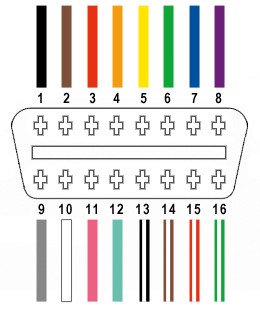
We will be utilizing only four essential wires from the 16 available on the OBD-II connector (referred to as OBD2C):
- Pin 4: Chassis ground (orange wire on OBD2C)
- Pin 6: CAN (J-2234) High (green wire on OBD2C)
- Pin 14: CAN (J-2234) Low (brown wire with white stripe on OBD2C)
- Pin 16: Battery power (green wire with white stripe on OBD2C)
Step-by-Step Guide to Building Your Homemade OBD2 to USB Cable
Let’s get started on building your DIY OBD2 cable. Follow these steps carefully to create a functional cable for basic OBD2 diagnostics.
Step 1: Prepare the OBD2 Cable
Start by preparing the OBD2 cable. Based on common practices for data transmission, twisting wire pairs can help reduce interference. Begin by removing the outer sheath and shielding from the OBD2C to expose the internal wires. Carefully separate the four wires we’ll be using (pins 4, 6, 14, and 16) from the rest. To keep the unused wires organized and out of the way, you can bundle them together and secure them with a zip tie.
Step 2: Prepare the 4-Pin Connector Wires
The wires within the OBD2C are quite thin (26AWG), while the pins of the 4-pin connector (4PC) are designed for slightly thicker wires (22AWG). To ensure a secure connection, we need to thicken the ends of the OBD2C wires.
The wires come pre-stripped with a small amount of exposed wire. Increase the exposed wire length to about 3/8 inch. Then, carefully fold the exposed wire back onto itself and twist it to effectively double its thickness. This will help it fit more snugly within the 4PC pins.
The 4PC kit includes rubber seals, which are important for environmental protection and strain relief. Slide one rubber seal onto each of the four prepared wires.
Step 3: Attach Wires to Connector Pins (Soldering or Crimping)
Now it’s time to attach the prepared wires to the pins of the 4-pin connector. Each pin has two sets of prongs. The front prongs are designed to clamp onto the exposed wire, and the rear prongs are for securing the rubber seal.
Insert the exposed, thickened wire into the front of a pin, ensuring it aligns with the front set of prongs. You’ll notice how thin the wire is compared to the pin connector. Using needle-nose pliers can be helpful to hold the wire in place during the next step.
Soldering (Recommended): Soldering provides a strong and reliable electrical and mechanical connection. If you choose to solder, apply a small amount of solder to the area where the wire meets the pin. Ensure the solder flows smoothly and creates a solid joint. If you are new to soldering, there are many helpful tutorials available online, such as Soldering Basics YouTube Tutorial.
Crimping (Alternative): If you have a Molex crimping tool, this is the ideal method for securing the pins. If not, needle-nose pliers can be used with care.
Using needle-nose pliers, carefully fold one of the front prongs over the wire. Repeat for the other prong, ensuring a tight crimp. You can find helpful crimping techniques on platforms like YouTube, such as Crimping Connector Pins Tutorial. For added security, you can gently squeeze the prongs further with pliers, but be careful not to damage the pin.
Step 4: Secure the Rubber Seal
Once the wire is securely attached to the pin, slide the rubber seal up the wire until it sits between the rear set of prongs on the pin. Use the same crimping or pliers technique as before to fold these rear prongs over the rubber seal. This secures the seal and provides strain relief for the wire.
Repeat steps 2-4 for the remaining three wires and pins.
Step 5: Wire Pairing and Twisting (Recommended)
To minimize potential signal interference, it is recommended to twist certain wire pairs together. Pair and twist the wires as follows:
- Pin 4 (orange) and Pin 16 (green with white stripe)
- Pin 6 (green) and Pin 14 (brown with white stripe)
Twisting these pairs can improve signal integrity for your homemade OBD2 to USB cable.
Step 6: Final Assembly and Connector Insertion
Finally, insert the pins into the 4-pin connector housing in the correct orientation. Refer to the diagram below:
- Pin 14 (brown with white stripe) > Connector slot A
- Pin 6 (green) > Connector slot B
- Pin 16 (green with white stripe) > Connector slot C
- Pin 4 (orange) > Connector slot D
Push each pin into the rear of the connector housing until you hear a click, indicating that it is securely locked in place. Using needle-nose pliers can help to gently pull the wire from the back to ensure the pin is fully seated and locked.
Completion and Testing
Congratulations! You have now completed your homemade OBD2 to USB cable.
Before using it for critical diagnostics, it’s crucial to test your cable. Connect it to your vehicle and a compatible OBD2 software on your computer. You can attempt to read and clear a non-critical diagnostic trouble code to verify functionality.
Important Considerations and Disclaimer
This guide provides instructions for creating a homemade OBD2 to USB cable for basic diagnostic purposes. It is essential to understand the risks involved in DIY automotive electronics.
- Risk of Damage: Incorrect wiring can potentially damage your vehicle’s ECU or your computer. Double-check all connections and pinouts before connecting the cable to your vehicle.
- Limited Functionality: This homemade cable is intended for basic OBD2 functions like reading and clearing diagnostic codes. It may not support advanced features or protocols.
- Software Compatibility: Ensure you use OBD2 software that is compatible with a basic OBD2 to USB connection.
Disclaimer: This DIY project is undertaken at your own risk. We are not responsible for any damage or issues that may arise from following this guide.
If any step is unclear, or you are unsure about any part of the process, please seek clarification or consult with someone experienced in automotive electronics before proceeding.