Embarking on a DIY project to build a custom head-up display (HUD) for your car is an exciting endeavor. Integrating an OBD2 Bluetooth interface can unlock a wealth of real-time vehicle data, projecting it directly into your line of sight for safer and more informed driving. This post details the journey, challenges, and breakthroughs encountered while developing such a system.
Initially, the project hit a snag with the OLED screen. After connecting and attempting to initialize it with DIYMall libraries, the results were less than ideal. Instead of a crisp display, only random pixels illuminated, stubbornly refusing to turn off after initialization. This indicated a potential hardware issue with the screen itself – a frustrating, but common hurdle in DIY electronics.
To overcome this display hurdle, a decision was made to switch to a different OLED screen, opting for a model known for its positive reviews and compatibility with the Adafruit OLED screen library. This specific screen, readily available online, promised a smoother integration and better performance for the HUD project.
Safety is paramount when working with car electronics. To protect the system from potential power surges, adding a fuse to the +12V power line from the car was deemed essential. Instead of standard car fuses, a 2A fast blow fuse was selected, paired with convenient 5x20mm fuse PCB mounts. These components ensure rapid circuit breaking in case of overcurrent, safeguarding the delicate electronics of the HUD.
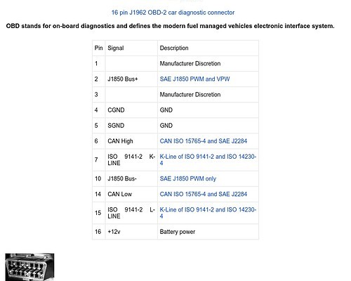
The next crucial step involved understanding and verifying the OBDII extension cable. First, the standard pinout of the car-side OBDII connector was consulted to identify the essential pins for this project.
From the comprehensive OBDII pinout diagram, it became clear that only a subset of pins were necessary for the intended HUD functionality. Specifically, five pins were identified as critical:
- +12V: Power supply for the HUD system.
- Chassis Ground: Ground connection to the car’s chassis.
- Signal Ground: Ground for signal circuits, ensuring signal integrity.
- CAN High: CAN bus high signal for data communication.
- CAN Low: CAN bus low signal for data communication.
With the required OBDII pins identified, the next step was to map these to the wires of the OBDII extension plug. Close examination of the extension plug revealed pin labeling. Using a multimeter in continuity mode, each pin of interest was tested to determine the corresponding wire. This meticulous process ensured accurate identification of each wire within the extension cable.
To enhance the HUD’s projection aspect, an interesting idea emerged – utilizing a scope lens protector typically used for gun sights. These protectors, designed to be transparent and mounted on rails, could potentially serve as an ideal screen for reflecting the display into the driver’s line of sight. This innovative approach offers a compact and robust solution for the HUD display component.
The project is progressing steadily, with key components identified and initial challenges addressed. The next crucial steps involve practical testing:
- Connecting the modified OBDII extension plug to the car’s OBDII port to verify the identified connections and power delivery.
- Testing the new replacement OLED screen to ensure it functions correctly and resolves the initial display issues.
These upcoming tests will validate the groundwork laid and pave the way for further development of the custom OBD2 Bluetooth head-up display.
[