For car enthusiasts and DIY mechanics, having the ability to perform your own vehicle diagnostics can save time and money. Building your own Diy Obd2 Cable is a straightforward project that allows you to connect your car to diagnostic tools for reading error codes and monitoring vehicle data. This guide provides a simple, step-by-step approach to creating your own OBD2 cable, perfect for basic automotive diagnostic needs.
Tools and Parts You’ll Need
Before starting, gather the necessary tools and parts. This project requires minimal tools and readily available components.
- Wire strippers/cutters
- Needle-nose pliers
- Molex crimping tool (optional, but recommended for a professional finish)
- Soldering iron and solder (recommended for a more secure connection)
- 4-pin connector (link to part used; pin/wire size = 22-16AWG; insulation/seal size = 1.3-1.7mm) – 4-Pin Connector for DIY OBD2 Cable Projects
- OBD-II Cable (link to part used) – OBD2 Extension Cable for DIY Wiring
If you have spare automotive wire, you can purchase just the female OBD-II connector and wire the 4 necessary connections yourself, potentially saving on costs. Ensure you select a 4-pin connector compatible with your wire gauge if you choose this route.
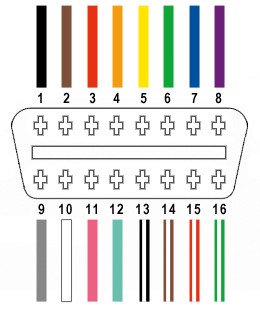
Only four wires from the 16 available in the OBD-II connector are essential for basic diagnostic functions:
- Pin 4 (Chassis Ground) – Often an orange wire in the OBD2 cable.
- Pin 6 (CAN [J-2234] High) – Typically a green wire in the OBD2 cable.
- Pin 14 (CAN [J-2234] Low) – Usually a brown wire with a white stripe in the OBD2 cable.
- Pin 16 (Battery Power) – Commonly a green wire with a white stripe in the OBD2 cable.
Step-by-Step Guide to Building Your DIY OBD2 Cable
Follow these steps to assemble your DIY OBD2 cable. Remember to work carefully and double-check connections to ensure proper functionality.
Step 1: Prepare the OBD2 Cable Wires
Begin by preparing the OBD2 cable. Carefully remove the outer sheath and shielding from the OBD2 cable to access the internal wires. Identify and separate the four wires you will be using: Chassis Ground (Pin 4), CAN High (Pin 6), CAN Low (Pin 14), and Battery Power (Pin 16). Bundle the remaining wires and secure them out of the way using a zip tie to keep your workspace tidy.
Step 2: Prepare the 4-Pin Connector Pins
The wires within the OBD2 cable are often a smaller gauge (26AWG) than ideally suited for the pins of the 4-pin connector (designed for 22AWG). To compensate for this difference in wire thickness, carefully strip approximately 3/8″ of insulation from the end of each of the four selected wires. Fold the exposed wire strands over onto themselves and twist them tightly to effectively double the wire thickness. This “thickening” ensures a better fit and connection within the 4-pin connector pins. Slide one of the provided rubber seals onto each of the prepared wires.
Step 3: Attach Wires to Pins (Soldering or Crimping)
Examine the pins for the 4-pin connector. You’ll notice two sets of prongs. The front prongs are designed to clamp onto the wire itself, while the rear prongs secure the wire’s insulation seal. Insert the prepared, thickened wire into the front section of the pin, ensuring the exposed wire aligns with the front prongs.
Soldering is highly recommended for this step to create a robust and electrically sound connection, especially given the small gauge of the OBD2 wires. Solder the wire to the pin connector, ensuring a good flow of solder for a strong joint. If you prefer crimping, or don’t have soldering equipment, proceed to the crimping step below.
(Optional – Crimping) If you are crimping, use a Molex crimping tool for the best results. If you don’t have a crimping tool, needle-nose pliers can be carefully used. Fold one prong at a time over the exposed wire, ensuring a tight crimp. For added security, you can gently squeeze the crimped prongs further with pliers.
Step 4: Secure the Wire Seal with Connector Pins
Slide the rubber seal up the wire until it sits snugly against the rear prongs of the connector pin. Use the same crimping or pliers technique as in Step 3 to fold these rear prongs over the rubber seal. This secures the seal and provides strain relief for the wire.
Step 5: Wire Pairing and Twisting (Recommended)
While not strictly necessary, it’s recommended to twist pairs of wires together. This practice, common in data communication wiring, can help reduce electromagnetic interference and improve signal integrity. Pair and twist the wires as follows:
- Pin 4 (orange – Chassis Ground) with Pin 16 (green w/white stripe – Battery Power)
- Pin 6 (green – CAN High) with Pin 14 (brown w/white stripe – CAN Low)
Step 6: Final Connector Assembly and Testing
Insert the completed pins into the 4-pin connector housing in the correct orientation as shown below:
- Pin 14 (brown w/white stripe – CAN Low) > Connector Slot A
- Pin 6 (green – CAN High) > Connector Slot B
- Pin 16 (green w/white stripe – Battery Power) > Connector Slot C
- Pin 4 (orange – Chassis Ground) > Connector Slot D
Push each pin into the rear of the connector housing until you hear a click, indicating it is securely locked in place.
Testing Your DIY OBD2 Cable
Your DIY OBD2 cable is now complete! Connect it to your vehicle and a compatible OBD2 diagnostic tool to test its functionality. You can use it to read and clear diagnostic trouble codes, and access live engine data.
By following these steps, you can create your own functional DIY OBD2 cable, enabling you to perform basic car diagnostics and maintenance tasks at home. This project is a great introduction to automotive wiring and can be a valuable tool for any car owner.