For car enthusiasts and DIYers, understanding your vehicle’s diagnostics is invaluable. While professional scan tools offer comprehensive features, building your own Diy Obd2 Bluetooth Adapter can be a rewarding and cost-effective project. This guide will walk you through the process of creating a basic OBD2 adapter, allowing you to tap into your car’s data for preliminary diagnostics and troubleshooting.
Disclaimer: Before we begin, it’s crucial to understand that this is a DIY project for informational and educational purposes. I am sharing my personal experience and the steps that worked for me. I am not a professional automotive technician, and this guide is not a substitute for professional advice. Proceed at your own risk. Incorrect wiring or usage could potentially damage your vehicle’s electronic control unit (ECU) or cause other issues. By following these steps, you acknowledge and accept full responsibility for any outcomes.
Tools and Parts You’ll Need
To embark on this diy obd2 bluetooth adapter project, gather the following tools and components:
- Wire strippers/cutters: Essential for preparing wires.
- Needle-nose pliers: Helpful for manipulating small components.
- Molex crimping tool (Optional but Recommended): For secure and professional crimping of connectors.
- Soldering iron (Recommended): For a more robust and reliable connection, although crimping can suffice.
- 4-pin connector: This will interface with your OBD2 cable. (Example Part Link; Ensure pin/wire size compatibility: 22-16AWG; insulation/seal size: 1.3-1.7mm)
- OBD-II Cable: Provides the standard OBD2 interface to connect to your vehicle. (Example Part Link)
For cost savings, if you have spare automotive-grade wire, you can purchase just the female OBD-II connector and wire the 4 necessary connections directly. Ensure your wire gauge matches the 4-pin connector specifications.
Understanding the OBD-II Connector Wiring
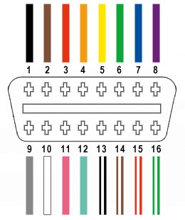
The OBD-II connector (OBD2C) has 16 pins, but for a basic adapter focused on CAN bus communication – commonly used for diagnostics – we only need to utilize four key pins:
- Pin 4 (Chassis Ground): Provides the ground connection for the circuit (typically an orange wire on the specified OBD2C).
- Pin 6 (CAN High [J-2284]): Carries the CAN bus high signal (typically a green wire on the specified OBD2C).
- Pin 14 (CAN Low [J-2284]): Carries the CAN bus low signal (typically a brown wire with a white stripe on the specified OBD2C).
- Pin 16 (Battery Power): Supplies power to the adapter (typically a green wire with a white stripe on the specified OBD2C).
Step-by-Step Guide to Building Your DIY OBD2 Adapter
1. Preparing the OBD-II Cable Wires:
Begin by carefully stripping back the outer sheath and shielding of the OBD-II cable to access the individual wires. Identify and separate the four wires corresponding to pins 4, 6, 14, and 16 as listed above. Bundle and secure the remaining 12 wires out of the way using a zip tie to prevent accidental shorts or interference.
2. Preparing Wires for the 4-Pin Connector:
A common challenge when building a diy obd2 bluetooth adapter arises from wire gauge differences. The wires in the OBD-II cable are often 26AWG, while the pins for the 4-pin connector (4PC) are designed for 22AWG. To compensate for this, carefully strip approximately 3/8″ of insulation from the end of each of the four selected wires. Fold the exposed wire strands over onto themselves, twisting them to effectively thicken the wire gauge, ensuring a better fit within the 4-pin connector pins. Slide a rubber seal (included with the 4PC kit) onto each wire.
3. Inserting Wires into 4-Pin Connector Pins:
Examine the pins for the 4-pin connector. You’ll notice two sets of prongs. The inner prongs are designed to crimp onto the exposed wire, and the outer prongs crimp onto the wire seal. Insert the prepared wire into the pin, aligning the exposed wire within the inner set of prongs. Due to the small wire gauge, using needle-nose pliers to hold the wire in position during the next step is highly recommended.
4. Soldering the Wires to the Pins (Recommended):
Soldering provides a superior electrical and mechanical connection for your diy obd2 bluetooth adapter. If you are comfortable soldering, apply a small amount of solder to the inner prongs of the connector pin, ensuring it flows and creates a solid bond with the wire. This is especially beneficial given the thin gauge of the OBD-II cable wires. If you are new to soldering, numerous helpful tutorials are available online, such as this YouTube video offering soldering tips and tricks.
5. Crimping the Connector Pins (Alternative Method):
If you prefer not to solder, or if you have a Molex crimping tool, you can crimp the connector pins. A crimping tool provides the most reliable crimped connection. However, if you don’t have one, needle-nose pliers can be used. Carefully fold one of the inner prongs over the wire using the pliers at an angle, then repeat for the other prong. Refer to online resources like this YouTube video for guidance on crimping techniques without a specialized tool. For added security, you can gently further compress the crimped prongs with pliers, but avoid excessive force.
6. Crimping the Seal Prongs:
Slide the rubber seal up the wire until it sits between the outer set of prongs on the connector pin. Using the same crimping technique (or crimping tool), fold the outer prongs over the rubber seal, securing it in place and providing strain relief and environmental protection.
7. Wire Pairing (Recommended):
While the exact reason isn’t definitively established, many DIY guides recommend twisting pairs of wires together. This may offer some level of noise reduction or signal integrity improvement. Pair and twist the wires as follows:
- Pin 4 (orange) / Pin 16 (green w/white stripe)
- Pin 6 (green) / Pin 14 (brown w/white stripe)
8. Inserting Pins into the 4-Pin Connector Housing:
Insert the completed pins into the 4-pin connector housing (4PC) in the correct orientation as shown below:
- Pin 14 (brown w/white stripe) > Connector Slot A
- Pin 6 (green) > Connector Slot B
- Pin 16 (green w/white stripe) > Connector Slot C
- Pin 4 (orange) > Connector Slot D
Push each pin into the rear of the connector housing until you hear an audible “click,” indicating it is locked securely in place. You can use needle-nose pliers to gently pull on the wire from the rear to ensure the pin is properly seated and locked.
Testing Your DIY OBD2 Adapter
Congratulations! Your basic diy obd2 bluetooth adapter is now complete.
You can now test your adapter by connecting it to your vehicle’s OBD2 port and using a compatible OBD2 diagnostic scanner or software. In a successful test, this DIY adapter was used to check and clear a self-induced error code.
Expanding to Bluetooth Functionality
This guide focuses on creating the basic wired OBD2 adapter. To achieve true diy obd2 bluetooth adapter functionality, the next step would involve integrating a Bluetooth module. This module would connect to the 4-pin connector you’ve created and wirelessly transmit the OBD2 data to your smartphone, tablet, or computer. Exploring Bluetooth modules like the HC-05 or similar, and researching OBD2 Bluetooth adapter schematics, will be the next exciting phase in enhancing this project.
If any step of this guide is unclear, or if you require further clarification, please don’t hesitate to ask for more details or photos.