As a seasoned auto repair expert at obd2global.com, I’m here to demystify a crucial aspect of modern vehicle diagnostics: the connection between CAN bus and OBD2. If you’re looking to understand how these two technologies intertwine to help mechanics and enthusiasts alike access vehicle data, you’ve come to the right place. This guide will delve into the specifics of “Can Bus To Obd2”, offering a comprehensive and SEO-optimized explanation exceeding the depth of the original article, ensuring you grasp this essential automotive concept.
Understanding OBD2 and Its Diagnostic Power
OBD2, or On-Board Diagnostics II, is your car’s built-in self-diagnostic system. Think of it as a standardized language that allows you to communicate with your vehicle’s computer. This protocol is essential for retrieving diagnostic trouble codes (DTCs) and accessing real-time data through the OBD2 connector.
You’re likely already familiar with OBD2 in some form. The dreaded malfunction indicator light (MIL), often called the “check engine light,” is an OBD2 indicator signaling an issue within your vehicle. When you take your car to a mechanic, they use an OBD2 scanner to pinpoint the problem.
This scanner connects to the OBD2 16-pin connector, usually located near the steering wheel. It sends ‘OBD2 requests’ to the car, and in turn, the car responds with ‘OBD2 responses’. These responses can contain a wealth of information, from speed and fuel level to those crucial Diagnostic Trouble Codes (DTCs), significantly speeding up the troubleshooting process.
Understanding OBD2: On-Board Diagnostics and the Malfunction Indicator Light (MIL).
OBD2 Compatibility: Is Your Car Equipped?
The question on many minds is, “Does my car support OBD2?” The answer is overwhelmingly yes, especially for newer, non-electric vehicles. The vast majority of these vehicles not only support OBD2 but also utilize CAN bus as their communication network.
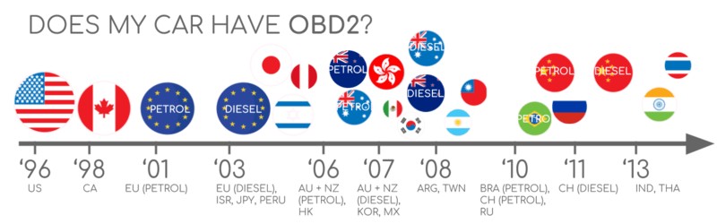
However, it’s worth noting that the presence of a 16-pin OBD2 connector doesn’t automatically guarantee OBD2 compliance, particularly in older models. To confirm, consider the vehicle’s origin and year of manufacture:
OBD2 Compliance Guide: Determine if Your Car Supports OBD2 based on Region and Year.
A Look Back: The History of OBD2 and CAN Bus Integration
OBD2’s roots trace back to California, where the California Air Resources Board (CARB) mandated OBD systems in all new cars from 1991 onwards for emission control. The Society of Automotive Engineers (SAE) further refined this by recommending the OBD2 standard, standardizing DTCs and the OBD connector across different manufacturers under SAE J1962.
The OBD2 standard was progressively implemented globally:
- 1996: OBD2 became compulsory in the USA for cars and light trucks.
- 2001: The EU mandated OBD2 for gasoline cars.
- 2003: OBD2 adoption extended to diesel cars in the EU (EOBD).
- 2005: OBD2 became a requirement for medium-duty vehicles in the US.
- 2008: US vehicles were required to use ISO 15765-4 (CAN) as the foundation for OBD2 communication, solidifying the “can bus to obd2” link.
- 2010: OBD2 compliance was extended to heavy-duty vehicles in the US.
OBD2 History: From Emission Control Origins to CAN Bus Integration.
OBD2 History Timeline: Key Milestones in On-Board Diagnostics Development.
OBD2 Future: Envisioning OBD3, Remote Diagnostics, and IoT Integration.
The Future Trajectory of OBD2 and CAN Bus
While OBD2 remains a cornerstone of vehicle diagnostics, its future is evolving. Originally designed for emission control, its relevance to electric vehicles (EVs) is different. Interestingly, standard OBD2 is not mandatory for EVs, and most modern EVs don’t fully support standard OBD2 requests. Instead, they often utilize OEM-specific UDS communication, making data extraction challenging without specialized knowledge or reverse engineering efforts. However, resources and case studies exist for accessing data from EVs like Tesla, Hyundai/Kia, Nissan, and VW/Skoda, showcasing the ongoing efforts in this area.
Emerging protocols like WWH-OBD (World Wide Harmonized OBD) and OBDonUDS (OBD on UDS) are being developed to address limitations in OBD2, particularly in data richness and lower-layer protocols. These aim to enhance OBD communication by using UDS protocol as a base. Understanding UDS is increasingly important in the context of modern vehicle diagnostics.
Looking further ahead, OBD3 envisions incorporating telematics into all vehicles. This concept involves adding a radio transponder to vehicles, enabling wireless transmission of VIN and DTCs to a central server for automated emission checks and diagnostics. Devices like CANedge2 WiFi CAN logger and CANedge3 3G/4G CAN logger already facilitate CAN or OBD2 data transfer via WiFi/cellular networks, paving the way for OBD3. However, concerns about surveillance and data privacy present political hurdles for widespread OBD3 adoption.
Another significant trend is the debate around third-party access to OBD2 data. Originally intended for repair shop servicing, OBD2 is now extensively used by third parties for real-time data generation through OBD2 dongles and CAN loggers. However, some automotive manufacturers are pushing to restrict this access, proposing to centralize data collection and potentially limit third-party access to vehicle data, raising questions about the future of independent automotive data services.
OBD2 Future in Electric Vehicles: Potential Shifts in Data Access and Diagnostics.
Deep Dive into OBD2 Standards and CAN Bus
To truly grasp “can bus to obd2”, it’s essential to understand the standards that govern them. OBD2 operates as a higher-layer protocol, a language built upon a communication method. CAN bus serves as this communication method, akin to a phone line. This parallel places OBD2 alongside other CAN-based higher-layer protocols like J1939, CANopen, and NMEA 2000.
OBD2 standards define the OBD2 connector, lower-layer protocols, OBD2 parameter IDs (PIDs), and much more. These standards can be mapped to the 7-layer OSI model, with both SAE and ISO standards covering various layers, reflecting US (SAE) and EU (ISO) standardization efforts. Many of these standards are technically very similar, such as SAE J1979 and ISO 15031-5, or SAE J1962 and ISO 15031-3.
OBD2 and CAN Bus in the OSI Model: Illustrating Protocol Layers and Standards.
The OBD2 Connector: Your Physical Interface to Vehicle Data [SAE J1962]
The 16-pin OBD2 connector, detailed in SAE J1962 / ISO 15031-3, is the physical gateway to accessing your car’s data. This Data Link Connector (DLC) is designed for easy access.
OBD2 Connector Pinout: Type A Socket and Pin Functionality.
Key features of the OBD2 connector include:
- Location near the steering wheel, though it might be concealed.
- Pin 16 providing battery power, often active even when the ignition is off.
- Pinout configuration varying based on the communication protocol used.
- Common use of CAN bus as the lower-layer protocol, typically connecting pins 6 (CAN-H) and 14 (CAN-L).
OBD2 Connector Types: A vs. B
You may encounter Type A and Type B OBD2 connectors. Type A is standard in cars, while Type B is more common in medium and heavy-duty vehicles.
While both types share similar pinouts, they differ in power supply output (12V for Type A, 24V for Type B) and often baud rates (500K for cars, 250K or 500K for heavy-duty vehicles).
Visually, Type B connectors have an interrupted groove in the middle, distinguishing them from Type A. Type B OBD2 adapter cables are compatible with both Type A and B sockets, but Type A adapters will not fit into Type B sockets.
OBD2 Connector Types A and B: Distinguishing Features and Applications.
OBD2 and CAN Bus: ISO 15765-4 and Diagnostics over CAN
Since 2008, CAN bus has been the mandatory lower-layer protocol for OBD2 in US vehicles, as per ISO 15765. This standard, ISO 15765-4 (Diagnostics over CAN or DoCAN), outlines specific constraints on the CAN standard (ISO 11898) for diagnostic purposes.
ISO 15765-4 standardizes the CAN interface for diagnostic equipment, focusing on the physical, data link, and network layers, specifying:
- CAN bus bit-rates of 250K or 500K.
- Support for both 11-bit and 29-bit CAN IDs.
- Dedicated CAN IDs for OBD requests and responses.
- Diagnostic CAN frame data length limited to 8 bytes.
- Maximum OBD2 adapter cable length of 5 meters.
OBD2 and CAN Bus: The ISO 15765-4 Standard for Diagnostics over CAN.
OBD2 CAN Identifiers: 11-bit and 29-bit
OBD2 communication relies on request/response message exchanges. In most cars, 11-bit CAN IDs are used. The ‘Functional Addressing’ ID, 0x7DF, queries all OBD2-compatible ECUs for data on a requested parameter (ISO 15765-4). ‘Physical Addressing’ requests, using CAN IDs 0x7E0-0x7E7, target specific ECUs but are less common.
ECUs respond using 11-bit IDs in the range 0x7E8-0x7EF. The most frequent response ID is 0x7E8 (Engine Control Module – ECM), followed by 0x7E9 (Transmission Control Module – TCM).
Some vehicles, particularly vans and medium to heavy-duty vehicles, may utilize extended 29-bit CAN identifiers for OBD2. In these cases, the ‘Functional Addressing’ CAN ID is 0x18DB33F1. Responses use CAN IDs ranging from 0x18DAF100 to 0x18DAF1FF, commonly 18DAF110 and 18DAF11E. This response ID is sometimes represented in ‘J1939 PGN’ format, specifically PGN 0xDA00 (55808), which is designated as ‘Reserved for ISO 15765-2’ in the J1939-71 standard.
OBD2 Request and Response Frames: Structure and Parameter IDs (PIDs).
OBD2 CAN Bus Identifiers: Common IDs like 7DF, 7E8, and 7E0.
OBD2 vs. Proprietary CAN Protocols: A Parallel System
It’s crucial to understand that vehicle ECUs operate using OEM-specific proprietary CAN protocols, independent of OBD2. These protocols are unique to each manufacturer, vehicle model, and year. Interpreting this proprietary data is generally not possible without OEM tools or reverse engineering.
When connecting a CAN bus data logger to the OBD2 connector, you might observe OEM-specific CAN data alongside OBD2 data, typically broadcast at high rates. However, many newer vehicles employ a ‘gateway’ that restricts access to this proprietary CAN data through the OBD2 port, allowing only OBD2 communication.
Think of OBD2 as a secondary, higher-layer protocol operating in parallel with the OEM-specific protocol, primarily for standardized diagnostic access.
OBD2 vs. Proprietary CAN Bus: Differentiating Standard and OEM-Specific Data.
Bit-rate and ID Validation: Ensuring Correct Communication
OBD2 over CAN bus can utilize two bit-rates (250K, 500K) and two CAN ID lengths (11-bit, 29-bit), resulting in four potential combinations. Modern cars commonly use 500K and 11-bit IDs, but diagnostic tools must systematically validate these settings.
ISO 15765-4 provides a recommended initialization sequence to determine the correct combination. This process relies on the requirement that OBD2-compliant vehicles must respond to a specific mandatory OBD2 request, and that incorrect bit-rates will cause CAN error frames.
Newer versions of ISO 15765-4 account for OBD communication via OBDonUDS in addition to OBDonEDS. While this article primarily focuses on OBDonEDS (OBD on Emission Diagnostic Service), OBDonUDS (OBD on Unified Diagnostic Service) is also relevant, particularly in EU trucks/buses (WWH-OBD).
To differentiate between OBDonEDS and OBDonUDS, diagnostic tools may send UDS requests with 11-bit/29-bit functional address IDs for service 0x22 and data identifier (DID) 0xF810 (protocol identification). Vehicles supporting OBDonUDS should respond to this DID. However, OBDonEDS (also known as OBD2, SAE OBD, EOBD, or ISO OBD) remains prevalent in most non-EV cars today.
OBD2 Bit-rate and CAN ID Validation Flowchart: ISO 15765-4 Initialization Sequence.
Five Lower-Layer OBD2 Protocols: Beyond CAN Bus
While CAN bus (ISO 15765) is dominant for OBD2 today, especially in vehicles post-2008, older cars might use other lower-layer protocols. Understanding these is helpful when working with pre-2008 vehicles. Pinouts on the OBD2 connector can sometimes indicate the protocol in use.
- ISO 15765 (CAN bus): Mandatory in US cars since 2008 and widely used today.
- ISO14230-4 (KWP2000): Keyword Protocol 2000, common in 2003+ cars, particularly in Asia.
- ISO 9141-2: Used in EU, Chrysler, and Asian cars around 2000-2004.
- SAE J1850 (VPW): Predominantly used in older GM vehicles.
- SAE J1850 (PWM): Primarily used in older Ford vehicles.
OBD2 Five Lower-Layer Protocols: CAN, KWP2000, ISO9141, SAE J1850 VPW, and PWM.
ISO-TP: Transporting OBD2 Messages Over CAN [ISO 15765-2]
All OBD2 data transmitted over CAN bus utilizes ISO-TP (ISO 15765-2), a transport protocol enabling payloads exceeding the 8-byte CAN frame limit. This is essential for OBD2 functions like retrieving the Vehicle Identification Number (VIN) or Diagnostic Trouble Codes (DTCs). ISO 15765-2 manages segmentation, flow control, and reassembly of these larger messages.
For smaller OBD2 data packets that fit within a single CAN frame, ISO 15765-2 specifies the use of ‘Single Frame’ (SF) formatting. In SF, the first data byte (PCI field) indicates the payload length, leaving 7 bytes for OBD2 communication.
ISO 15765-2 Frame Types: Single Frame, First Frame, Consecutive Frame, and Flow Control.
Deciphering the OBD2 Diagnostic Message [SAE J1979, ISO 15031-5]
To better understand “can bus to obd2” communication, let’s examine a raw ‘Single Frame’ OBD2 CAN message. In simplified terms, an OBD2 message comprises an identifier, a data length indicator (PCI field), and the data itself. The data is further broken down into Mode, parameter ID (PID), and data bytes.
OBD2 Message Structure: Mode, Parameter ID (PID), and Data Bytes Explained.
OBD2 Request/Response Example: Vehicle Speed
Consider this example of requesting and receiving vehicle speed data. An external tool sends a request message to the car with CAN ID 0x7DF, containing two payload bytes: Mode 0x01 and PID 0x0D. The car responds with CAN ID 0x7E8 and three payload bytes, including the vehicle speed value in the fourth byte, 0x32 (decimal 50).
By consulting OBD2 PID documentation for PID 0x0D, we find that this value corresponds to a physical speed of 50 km/h. This illustrates the basic request-response mechanism and data interpretation in “can bus to obd2” communication.
OBD2 Request and Response Example: Requesting Vehicle Speed (PID 0x0D).
OBD2 PID 0x0D: Decoding Vehicle Speed Data.
The 10 OBD2 Services (Modes): Diagnostic Functions
OBD2 defines 10 diagnostic services, often referred to as modes. Mode 0x01 provides real-time data, while others are used for accessing and clearing diagnostic trouble codes (DTCs) or viewing freeze frame data.
Vehicles are not required to support all 10 OBD2 modes, and manufacturers may implement additional OEM-specific modes beyond these standardized ones.
In OBD2 messages, the mode is indicated in the second byte. In a request, the mode is directly specified (e.g., 0x01). In the response, 0x40 is added to the requested mode value (e.g., 0x41 for a response to mode 0x01).
OBD2 Services (Modes): Overview of the 10 Standardized Diagnostic Functions.
OBD2 Parameter IDs (PIDs): Accessing Specific Data
Within each OBD2 mode, Parameter IDs (PIDs) are used to specify the data being requested. For example, mode 0x01 includes approximately 200 standardized PIDs for real-time data such as speed, RPM, and fuel level. However, vehicles typically support only a subset of the available PIDs within a mode.
One PID, PID 0x00 in mode 0x01, is particularly important. If an emissions-related ECU supports any OBD2 services, it must support mode 0x01 PID 0x00. Responding to this PID indicates support for PIDs 0x01-0x20. Thus, PID 0x00 serves as a fundamental OBD2 compatibility test. Similarly, PIDs 0x20, 0x40, …, 0xC0 can be used to determine support for subsequent ranges of mode 0x01 PIDs.
OBD2 Request and Response Frames: Illustrating Mode and PID Structure.
OBD2 PID Overview Tool: Service 01 and Parameter Identification.
OBD2 PID Overview Tool: Simplifying Data Lookup
SAE J1979 and ISO 15031-5 appendices provide scaling information for standard OBD2 PIDs, enabling conversion of raw data into physical values. For quick PID lookups, consider using an OBD2 PID overview tool. This simplifies constructing OBD2 request frames and dynamically decoding responses, streamlining the process of working with “can bus to obd2” data.
OBD2 PID overview tool
Practical Guide: Logging and Decoding OBD2 Data via CAN Bus
Let’s walk through a practical example of logging OBD2 data using a CANedge CAN bus data logger. The CANedge allows configuration of custom CAN frames for transmission, making it ideal for OBD2 logging. Connecting it to your vehicle is straightforward using an OBD2-DB9 adapter cable.
OBD2 Data Logger Setup: CANedge and OBD2-DB9 Adapter Cable for PID Data Logging.
Supported PIDs Test Results: Reviewing Responses in asammdf.
Step #1: Bit-rate, ID, and Supported PID Validation
Following ISO 15765-4, determine the vehicle’s bit-rate and CAN IDs. Use CANedge for this validation process:
- Test at 500K bit-rate and check for successful transmission (if unsuccessful, try 250K).
- Use the verified bit-rate for subsequent communication.
- Send ‘Supported PIDs’ requests and analyze responses.
- Determine 11-bit vs. 29-bit IDs based on response IDs.
- Identify supported PIDs from response data.
Pre-configured settings are available to simplify these tests. Most 2008+ non-EV cars typically support 40-80 PIDs using 500K bit-rate, 11-bit CAN IDs, and the OBD2/OBDonEDS protocol.
Analyzing responses in software like asammdf reveals multiple responses to a single OBD request due to the use of the 0x7DF request ID, which queries all ECUs. Since all OBD2/OBDonEDS-compliant ECUs must support service 0x01 PID 0x00, numerous responses to this PID are common. Subsequent ‘Supported PIDs’ requests usually receive fewer responses as fewer ECUs support the extended PID ranges. Note that the ECM ECU (0x7E8) often supports all PIDs supported by other ECUs, suggesting that using ‘Physical Addressing’ with CAN ID 0x7E0 for subsequent communication can reduce bus load.
Step #2: Configuring OBD2 PID Requests for Logging
Once you know the supported PIDs, bit-rate, and CAN IDs, configure your data logger with the PIDs of interest.
Consider these factors:
- CAN IDs: Use ‘Physical Addressing’ request IDs (e.g., 0x7E0) to minimize multiple responses.
- Spacing: Introduce 300-500 ms delays between OBD2 requests to prevent ECU overload.
- Battery Drain: Implement triggers to stop transmissions when the vehicle is inactive to avoid battery drain.
- Filters: Apply filters to record only OBD2 responses, especially if OEM-specific CAN data is also present.
With these configurations, your data logger is ready to record raw OBD2 data over CAN bus.
Example CANedge OBD2 PID Request List: Configuring Transmit Messages.
OBD2 Data Visualization: Decoded and Plotted using asammdf and a DBC file.
Step #3: DBC Decoding of Raw OBD2 Data
To analyze and visualize logged OBD2 data, decode the raw data into physical values. Decoding information is available in ISO 15031-5/SAE J1979 and online resources like Wikipedia. A free OBD2 DBC file simplifies DBC decoding in most CAN bus software tools.
Decoding OBD2 data is more complex than standard CAN signals because different OBD2 PIDs share the same CAN ID (e.g., 0x7E8). Therefore, signal identification requires considering the CAN ID, OBD2 mode, and OBD2 PID. This ‘extended multiplexing’ approach is addressable using DBC files.
CANedge: Your OBD2 Data Logging Solution
The CANedge offers a straightforward solution for recording OBD2 data to SD cards (8-32 GB). Connect it to your vehicle to start logging and utilize free software/APIs and the OBD2 DBC for data analysis.
OBD2 logger intro CANedge
Multi-Frame OBD2 Communication Examples [ISO-TP]
While single-frame communication is common in OBD2, multi-frame communication, managed by ISO-TP (ISO 15765-2), is necessary for larger data sets. Multi-frame OBD2 exchanges involve flow control frames. A common approach is to transmit a static flow control frame approximately 50 ms after the initial request. CANedge configuration examples demonstrate this technique. Analyzing multi-frame OBD2 responses requires CAN software/API tools with ISO-TP support, such as CANedge MF4 decoders.
OBD2 Multi-Frame Request: Example Request for Vehicle Identification Number (VIN).
Example 1: Retrieving Vehicle Identification Number (VIN) via OBD2
The Vehicle Identification Number (VIN) is crucial for telematics and diagnostics. To retrieve the VIN using OBD2 requests, use mode 0x09 and PID 0x02:
OBD2 VIN Retrieval Example: Multi-Frame Request and Response Sequence.
The tester tool sends a Single Frame request with PCI field (0x02), service identifier (0x09), and PID (0x02). The vehicle responds with a First Frame containing PCI, length (0x014 = 20 bytes), mode (0x49), and PID (0x02). Following the PID is the Number Of Data Items (NODI) byte (0x01 in this case), indicating one VIN. The subsequent 17 bytes represent the VIN, which can be converted from HEX to ASCII.
Example 2: Multi-PID Request (6x) in OBD2
OBD2 allows requesting up to six mode 0x01 PIDs in a single request frame. The ECU responds with data for supported PIDs (omitting unsupported ones), potentially using multi-frame responses via ISO-TP.
This method enhances data collection efficiency, but the signal encoding becomes specific to the request, complicating the use of generic OBD2 DBC files. Therefore, this approach is generally not recommended for practical data logging unless specialized tools are used.
OBD2 Multi-PID Request Example: Trace of a Request for Multiple PIDs.
Decoding multi-PID responses via generic DBC files is challenging due to the payload structure and PID ordering. While technically feasible, it requires advanced scripting and potentially tracking request messages to interpret responses correctly. This complexity makes it less scalable and more difficult to generalize across different vehicles and PID configurations.
Example 3: Accessing OBD2 Diagnostic Trouble Codes (DTCs)
OBD2 mode 0x03, ‘Show stored Diagnostic Trouble Codes’, retrieves emissions-related DTCs. No PID is included in the request. The ECU responds with the number of stored DTCs (potentially zero) and the DTCs themselves, with each DTC occupying 2 bytes. Multi-frame responses are necessary when more than two DTCs are stored.
The 2-byte DTC value is structured according to ISO 15031-5/ISO 15031-6. The first 2 bits define the DTC category, and the remaining 14 bits form a 4-digit hexadecimal code. Decoded DTC values can be looked up using OBD2 DTC lookup tools.
OBD2 DTC Decoding: Structure and Interpretation of Diagnostic Trouble Codes.
OBD2 DTC Request and Response Example: CAN Bus Trace with Diagnostic Trouble Codes.
Real-World Applications: OBD2 Data Logging Use Cases
OBD2 data logging from cars and light trucks has diverse applications:
Vehicle Data Logging
OBD2 data can be leveraged to optimize fuel efficiency, enhance driving habits, test prototype components, and for insurance telematics.
obd2 logger
Real-time Vehicle Diagnostics
OBD2 interfaces enable real-time streaming of human-readable vehicle data for immediate diagnostics and issue identification.
obd2 streaming
Predictive Maintenance
IoT-connected OBD2 loggers facilitate remote vehicle monitoring for predictive maintenance, helping prevent breakdowns and optimize fleet management.
predictive maintenance
Vehicle Black Box Recording
OBD2 loggers can serve as ‘black boxes’ for vehicles, providing crucial data for incident analysis, warranty validation, and diagnostic insights.
can bus blackbox
Have an OBD2 data logging application? We’re here to help!
Contact us
Explore our guides for more in-depth introductions or download our comprehensive ‘Ultimate Guide’ PDF.
Ready to start logging or streaming OBD2 data?
Get your OBD2 data logger today!
Buy now Contact us
Further Reading
OBD2 DATA LOGGER: EASILY LOG & CONVERT OBD2 DATA
CANEDGE2 – PRO CAN IoT LOGGER
CAN BUS INTERFACE: STREAMING OBD2 DATA WITH SAVVYCAN