Navigating the complexities of modern vehicle diagnostics often involves deciphering various sensor readings provided by your OBD2 scanner. Among these, the Throttle Position (TP) sensor plays a crucial role in engine management. If you’ve encountered terms like “TP_B” or wondered about the meaning behind TP sensor readings in your OBD2 diagnostics, you’re in the right place. This article delves into understanding TP sensor readings in OBD2 systems, drawing from a real-world troubleshooting experience to shed light on potential issues and solutions.
Decoding TP Sensor Readings: A Practical OBD2 Diagnostic Experience
Recently, a car owner encountered perplexing readings from their TP and Accelerator Pedal Position (APP) sensors. Initially, suspecting a potential wiring or connection problem, they turned to the OBD2 scanner for insights. The readings revealed discrepancies between sensor pairs, specifically TP Sensor 1 and TP Sensor 2, as well as APP Sensor 1 and APP Sensor 2.
To illustrate, let’s examine the initial sensor readings before any intervention:
| Sensor | Undepressed Reading | Reading 1 | Reading 2 |
|---|---|---|---|
| APP #1 | 17.3 | 28.6 | 32.9 |
| APP #2 | 9.4 | 13.7 | 15.3 |
As observed, even in the undepressed state, there were noticeable differences between APP Sensor 1 and APP Sensor 2. Similarly, discrepancies were noted in the TP sensor readings (although specific TP readings were not initially charted in this “before” state, they were mentioned as significantly different in the original context).
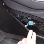
Suspecting an issue with the Accelerator Pedal Position (APP) sensor, particularly given the advice from a seasoned GM technician to check circuit wiring and APP sensor resistance, the car owner decided to replace the APP sensor. This decision was further influenced by the significant difference observed between TP Sensor 1 (TPS #1) and TP Sensor 2 (TPS #2) readings, with TPS #1 at 31.0% and TPS #2 at 39.8% in one instance.
The Impact of APP Sensor Replacement on TP Sensor Readings
After installing a new APP sensor, a comparative analysis was conducted to assess the changes in sensor readings. Focusing on matching the APP #2 reading of the new sensor to the old one by manually depressing the pedal, the following readings were obtained:
| Sensor | Undepressed Reading | Reading 1 | Reading 2 |
|---|---|---|---|
| APP #1 | 20.4 | 28.2 | 31.4 |
| APP #2 | 9.4 | 13.7 | 15.3 |
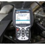
Alt text: OBD2 scanner screen showing live data stream with highlighted Throttle Position (TP) and Accelerator Pedal Position (APP) sensor readings, illustrating real-time vehicle diagnostics.
Even without pedal depression, a difference was evident compared to the initial readings. It’s important to note that while percentage values for APP sensors might vary slightly due to APP #2 being a backup sensor, TP sensors should ideally exhibit closely aligned percentage readings.
Further investigation into the TP sensor readings revealed a significant improvement post APP sensor replacement. By manually adjusting the pedal until TPS #1 reached 31.0%, TPS #2 now also read approximately 31%. This alignment indicated a positive shift in TP sensor correlation after addressing the APP sensor.
Alt text: Diagram showing the interconnected components of a vehicle’s throttle system, including the accelerator pedal, Accelerator Pedal Position (APP) sensor, throttle body, and Throttle Position (TP) sensor, emphasizing their functional relationship.
The 5V Reference Circuit and Sensor Interplay
The car owner, through online research, hypothesized that the issue might stem from a shared 5V reference circuit. It’s commonly understood that in many vehicles, TP Sensor 1 and APP Sensor 1 share a 5V reference circuit, and similarly, TP Sensor 2 and APP Sensor 2 share another 5V reference circuit.
Based on the observed readings and the impact of APP sensor replacement, it was deduced that a potential short circuit within the old APP sensor could have been influencing the TP sensor readings. By replacing the APP sensor, the disruption in the 5V reference circuit was likely resolved, leading to more accurate and consistent TP sensor data.
Conclusion: Learning from OBD2 TP Sensor Diagnostics
This real-world example underscores the importance of understanding sensor relationships and the insights OBD2 diagnostics can provide. While the car owner in this scenario isn’t a professional mechanic, their methodical approach to troubleshooting, combined with OBD2 scanner data interpretation and online research, led to a successful resolution.
Key takeaways from this experience include:
- TP sensor readings can be influenced by related sensors: An issue with the APP sensor can manifest as irregularities in TP sensor readings due to shared circuits.
- OBD2 scanners are invaluable tools for DIY diagnostics: They provide crucial data for understanding sensor behavior and identifying potential problem areas.
- Understanding 5V reference circuits is beneficial: Knowing how sensors are interconnected in the vehicle’s electrical system aids in effective troubleshooting.
While this specific case study focused on APP sensor impact on TP readings, it highlights the broader principle of systematic diagnostics in OBD2-equipped vehicles. For anyone facing similar OBD2 diagnostic puzzles, a step-by-step approach, combined with community knowledge and reliable resources like obd2global.com, can pave the way for effective solutions.
Disclaimer: This article is based on a personal experience and intended for informational purposes. Always consult your vehicle’s service manual and consider professional assistance for complex diagnostic and repair procedures.