As a seasoned auto repair expert at obd2global.com, I understand the frustrations of diagnosing vehicle issues, especially when communication problems arise with your OBD2 tools. Many DIY enthusiasts and professionals alike encounter challenges when working with the K line protocol in OBD2 systems. This guide will delve into the common issues and troubleshooting steps for K Line Obd2 communication, drawing inspiration from a recent user’s experience and expanding upon it to provide a comprehensive resource.
Understanding the K Line in OBD2
The K line is a crucial communication pathway in older OBD2 (On-Board Diagnostics II) systems, particularly those adhering to the ISO 9141-2 standard. Unlike the more modern CAN bus systems, K line communication is a single-wire, bidirectional protocol. This means that data is transmitted and received over the same wire, relying on voltage levels to represent binary information.
While CAN bus has become more prevalent in newer vehicles, K line is still found in many cars, especially models from the late 1990s to the mid-2000s, and even some later models for specific systems. Understanding how K line works is essential for effective diagnostics on these vehicles.
Common K Line OBD2 Communication Problems
Establishing a reliable K line connection for OBD2 diagnostics can be tricky. Here are some common pitfalls that can lead to communication failures:
1. Wiring and Circuit Issues:
- Incorrect Wiring: K line systems are sensitive to proper wiring. A misplaced wire, even slightly, can disrupt communication. This is especially true in DIY setups where errors can easily occur.
- Loose Connections: Weak or loose connections in your wiring can lead to intermittent or complete communication loss. Vibration and environmental factors can exacerbate this.
- Faulty Components: Resistors, transistors, or other electronic components in your K line interface circuit can fail, preventing proper signal transmission.
- Grounding Problems: Inadequate or improper grounding can introduce noise and interference, disrupting the sensitive K line signals.
2. Resistor Value Mismatches:
- Pull-up/Pull-down Resistors: K line circuits often rely on pull-up or pull-down resistors to define the signal’s idle state and ensure proper signal levels. Incorrect resistor values can lead to weak or distorted signals that the ECU (Engine Control Unit) cannot interpret.
- Termination Resistors: In some K line implementations, termination resistors are used to prevent signal reflections. Incorrect or missing termination resistors can cause communication errors.
3. Software and Protocol Issues:
- Incorrect Protocol Selection: OBD2 encompasses several communication protocols. If your diagnostic tool or software is not configured to use ISO 9141-2 (K line), communication will fail.
- Software Bugs: Glitches or bugs in your diagnostic software or Arduino code can prevent proper initialization and data exchange over the K line.
- Timing Issues: K line communication is timing-sensitive. Incorrect timing parameters in your code or interface can disrupt the data flow.
4. ECU Compatibility and Issues:
- ECU Not Responding: In some cases, the ECU itself might be faulty or not powered correctly, preventing it from responding to diagnostic requests.
- Protocol Mismatches (Vehicle Side): While adhering to ISO 9141-2, specific vehicle manufacturers might have slight variations in their K line implementation, leading to compatibility issues with generic tools.
Troubleshooting Steps for K Line OBD2 Communication Failure
Let’s outline a systematic approach to diagnose and resolve K line OBD2 communication problems, drawing upon a real-world example and expanding the troubleshooting process.
Scenario: A user built a K line OBD2 interface using an Arduino and encountered a persistent “init_success = 0” error, indicating a failure to establish communication. Let’s analyze this and provide broader troubleshooting steps.
Step 1: Verify the Circuit and Wiring
This is the first and most crucial step, especially for DIY interfaces.
- Double-Check Wiring: Carefully compare your circuit wiring against a reliable schematic diagram. Ensure every wire is connected to the correct pin on the Arduino, OBD2 connector, and electronic components. Pay close attention to the K line pin (typically pin 7 on the OBD2 connector for ISO 9141-2).
- Inspect Connections: Check for loose wires, cold solder joints, or any signs of poor connections. Resolder any suspicious joints and ensure wires are firmly seated in connectors.
- Component Verification: Confirm that you are using the correct electronic components (transistors, resistors, etc.) and that they are properly oriented. Verify resistor values using a multimeter to ensure they match the schematic. In the user’s case, resistor values are listed, but it’s essential to physically check them.
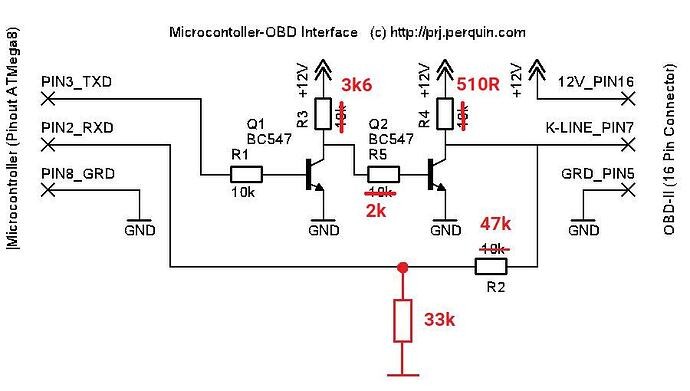 Circuit diagram for K Line OBD2 interface using Arduino
Step 2: Examine the Arduino Code
- Library Compatibility: Ensure you are using a compatible and correctly installed OBD2 library for Arduino (like the
OBD9141.hlibrary mentioned in the user’s code). Check the library documentation for specific setup requirements and examples. - Pin Definitions: Verify that the RX and TX pins defined in your code (
#define RX_PIN 8,#define TX_PIN 9) correctly correspond to the Arduino pins you’ve wired to your K line interface. Double-check if you are using AltSoftSerial or SoftwareSerial and if pin assignments are compatible. - Initialization Sequence: Review the OBD2 library’s initialization code (
obd.begin(altSerial, RX_PIN, TX_PIN);). Ensure the initialization sequence in your code matches the library’s requirements and the ISO 9141-2 protocol. - Baud Rate: K line communication typically operates at lower baud rates (e.g., 9600 bps). Confirm that your Arduino code and OBD2 library are configured for the correct baud rate.
- Debugging Output: Utilize
Serial.println()statements strategically in your code to monitor the program flow and variable values. This helps pinpoint where the initialization process might be failing, as seen in the user’s example whereinit_successis consistently 0.
Step 3: Power and Grounding Checks
- Power Supply: Ensure your Arduino and K line interface circuit are receiving stable and sufficient power. Verify the voltage levels with a multimeter.
- Ground Connections: Confirm that all ground connections are solid and properly connected to the vehicle’s ground (OBD2 connector pin 4 or 5). A poor ground is a frequent cause of communication problems.
Step 4: ECU and Vehicle Compatibility
- Vehicle Year and Model: Confirm that your vehicle is indeed K line based and compatible with the ISO 9141-2 protocol. Refer to your vehicle’s documentation or online resources to verify OBD2 protocol compatibility for your specific make, model, and year.
- ECU Power and Functionality: Rule out the possibility of a faulty ECU or issues with ECU power supply. While less common, ECU problems can prevent communication.
- Try a Known Working Vehicle: If possible, test your K line interface and code on a different vehicle known to use K line OBD2. This can help isolate whether the problem lies with your interface or the specific vehicle you are trying to diagnose.
Step 5: Advanced Diagnostics (Multimeter and Oscilloscope)
- Voltage Level Checks: Use a multimeter to measure voltage levels at various points in your K line circuit, including the K line pin on the OBD2 connector, transistor junctions, and resistor terminals. Compare these readings to expected values based on the circuit design.
- Signal Waveform Analysis (Oscilloscope): For more advanced troubleshooting, an oscilloscope can be invaluable. Connect the oscilloscope probe to the K line to observe the signal waveform during communication attempts. This can reveal signal distortion, noise, or timing issues that are not apparent with a multimeter alone.
Analyzing the User’s Example
In the provided user’s forum post, the repeated “Looping init_success = 0” output strongly suggests that the obd.init() function is failing. Based on the troubleshooting steps above, the user should:
- Carefully re-examine their circuit against the provided schematic, paying close attention to resistor values (R1=10K, R2=47K or 33K, R3=3.2K, R4=530, R5=2.2K) and transistor types (BC547). Resoldering is a good step, but verifying component values and wiring accuracy is crucial.
- Review the Arduino code, ensuring they are using the correct OBD2 library and that the pin definitions and initialization sequence are accurate.
- Check power and ground connections to the Arduino and the K line interface circuit.
Without further testing with a multimeter or oscilloscope, it’s difficult to pinpoint the exact problem. However, systematically following these troubleshooting steps will significantly increase the chances of resolving K line OBD2 communication issues.
Tips for Successful K Line OBD2 Communication
- Use Reliable Schematics: Always use verified and reliable circuit diagrams when building your K line interface.
- High-Quality Components: Employ quality electronic components and PCBs (if applicable) for better reliability and signal integrity.
- Shielded Wiring: Consider using shielded cables for K line connections, especially in noisy environments, to minimize interference.
- Proper Grounding: Pay meticulous attention to grounding. Use dedicated ground points and ensure low-resistance ground paths.
- Software Updates: Keep your OBD2 library and diagnostic software up to date to benefit from bug fixes and protocol improvements.
- Start Simple: Begin with basic communication tests (like reading generic PIDs) before attempting more complex diagnostic functions.
Conclusion
Troubleshooting K line OBD2 communication problems requires a methodical approach. By systematically checking wiring, components, software, and ECU compatibility, you can identify and resolve most issues. Remember to leverage online resources, vehicle-specific information, and diagnostic tools like multimeters and oscilloscopes when needed. By understanding the nuances of K line communication and following these troubleshooting steps, you can successfully diagnose and repair vehicles utilizing this protocol.