Are you fascinated by what’s happening under the hood of your car? Do you want to tap into the wealth of data your vehicle’s computer systems generate? With the power of Arduino, the MCP2515 CAN bus controller, and the OBD2 standard, you can unlock a real-time stream of information about your car’s performance. This guide will walk you through the basics of using the Mcp2515 Arduino Obd2 setup to monitor your engine speed, a crucial parameter for understanding your vehicle’s operation.
Understanding OBD2 and Engine Speed (PID 0x0C)
Modern vehicles are equipped with an On-Board Diagnostics II (OBD2) system. This standardized system allows you to access diagnostic information and real-time data about various vehicle parameters, from engine temperature to oxygen sensor readings. These parameters are identified by specific codes known as Parameter IDs (PIDs).
One of the most fundamental PIDs is PID 0x0C, which represents Engine RPM (Revolutions Per Minute), or engine speed. Knowing your engine speed is essential for understanding how your engine is performing under different conditions – idling, accelerating, or cruising. By monitoring engine speed, you can gain insights into fuel efficiency, transmission behavior, and overall engine health.
Setting Up Your Arduino with MCP2515 for OBD2 Communication
To communicate with your car’s OBD2 system using Arduino, you’ll need a few key components:
- Arduino Board: Any Arduino board compatible with the SPI interface will work (Uno, Nano, Mega, etc.).
- MCP2515 CAN Bus Controller Module: This module allows your Arduino to communicate over the Controller Area Network (CAN) bus, the backbone of OBD2 communication in most modern vehicles.
- CAN Transceiver: Often integrated into MCP2515 modules, the transceiver physically interfaces with the CAN bus wiring.
- OBD2 Connector (DB9 or Cable with OBD2 Plug): To connect to your car’s OBD2 port, typically located under the dashboard.
- Wiring: To connect the MCP2515 module to your Arduino and OBD2 connector.
The basic connection involves linking the SPI pins of the MCP2515 (CS, SO, SI, SCK) to the Arduino’s SPI pins. You’ll also need to connect the CAN transceiver pins (CANH, CANL) to the appropriate pins on your OBD2 connector. Refer to the documentation for your specific MCP2515 module and OBD2 connector for precise wiring details.
Arduino Code for Requesting Engine Speed (PID 0x0C)
The following Arduino code snippet provides a foundation for requesting engine speed (PID 0x0C) from your vehicle’s OBD2 system. This code initializes the MCP2515, sends a CAN message requesting PID 0x0C, and then listens for and displays any received CAN messages.
#include <mcp_can.h>
#include <SPI.h>

#define standard 0 // 7E0/8 = Engine ECM // 7E1/9 = Transmission ECM

#if standard == 1
  #define LISTEN_ID 0x7EA
  #define REPLY_ID 0x7E0
  #define FUNCTIONAL_ID 0x7DF
#else
  #define LISTEN_ID 0x98DAF101
  #define REPLY_ID 0x98DA01F1
  #define FUNCTIONAL_ID 0x98DB33F1
#endif

// CAN TX Variables
unsigned long prevTx = 0;
unsigned int invlTx = 1000;
byte txData[] = {0x02, 0x01, 0x0C, 0x55, 0x55, 0x55, 0x55, 0x55}; // Request PID 0C (Engine Speed)

// CAN RX Variables
unsigned long rxID;
byte dlc;
byte rxBuf[8];
char msgString[128]; // Array to store serial string

// CAN Interrupt and Chip Select Pins
#define CAN0_INT 2    /* Set INT to pin 2 (This rarely changes) */
MCP_CAN CAN0(10);     /* Set CS to pin 9 (Old shields use pin 10) */

void setup(){
  Serial.begin(115200);
  while(!Serial);

  // Initialize MCP2515 running at 8MHz with a baudrate of 500kb/s
  if(CAN0.begin(MCP_STDEXT, CAN_500KBPS, MCP_8MHZ) == CAN_OK)
    Serial.println("MCP2515 Initialized Successfully!");
  else{
    Serial.println("Error Initializing MCP2515... Permanent failure! Check your code & connections");
    while(1);
  }

  // Extended ID Filters (Adjust as needed for your vehicle)
  CAN0.init_Mask(0,0x90FF0000);
  CAN0.init_Filt(0,0x90DA0000);
  CAN0.init_Filt(1,0x90DB0000);
  CAN0.init_Mask(1,0x90FF0000);
  CAN0.init_Filt(2,0x90DA0000);
  CAN0.init_Filt(3,0x90DB0000);
  CAN0.init_Filt(4,0x90DA0000);
  CAN0.init_Filt(5,0x90DB0000);

  CAN0.setMode(MCP_NORMAL);                     // Set operation mode to normal
  pinMode(CAN0_INT, INPUT);                         // Configuring pin for /INT input

  Serial.println("Simple CAN OBD-II PID Request");
}

void loop(){
  if(!digitalRead(CAN0_INT)){                      // If CAN0_INT pin is low, read receive buffer
    CAN0.readMsgBuf(&rxID, &dlc, rxBuf);         // Get CAN data

    // Display received CAN data
    if((rxID & 0x80000000) == 0x80000000)     // Determine if ID is extended
      sprintf(msgString, "Extended ID: 0x%.8lX DLC: %1d Data:", (rxID & 0x1FFFFFFF), dlc);
    else
      sprintf(msgString, "Standard ID: 0x%.3lX DLC: %1d Data:", rxID, dlc);
    Serial.print(msgString);

    if((rxID & 0x40000000) == 0x40000000){    // Determine if message is a remote request frame.
      sprintf(msgString, " REMOTE REQUEST FRAME");
      Serial.print(msgString);
    } else {
      for(byte i = 0; i<dlc; i++){
        sprintf(msgString, " 0x%.2X", rxBuf[i]);
        Serial.print(msgString);
      }
    }
    Serial.println();
  }

  // Send PID 0C request every 1000ms (1 second)
  if((millis() - prevTx) >= invlTx){
    prevTx = millis();
    if(CAN0.sendMsgBuf(FUNCTIONAL_ID, 8, txData) == CAN_OK){
      Serial.println("Message Sent Successfully!");
    } else {
      Serial.println("Error Sending Message...");
    }
  }
}
Explanation of the Code:
- Includes:
mcp_can.handSPI.hlibraries are included for MCP2515 CAN communication and SPI interface respectively. Make sure you have themcp_can.hlibrary installed in your Arduino IDE. - CAN Definitions:
LISTEN_ID,REPLY_ID, andFUNCTIONAL_IDare defined for CAN message addressing. The code supports both standard (11-bit) and extended (29-bit) CAN IDs. The#if standard == 0block is configured for extended IDs, which are commonly used in modern OBD2 implementations. txData[]Array: This is the crucial part for requesting PID 0x0C.0x02: Service 01, indicating a request for current data.0x01: Service 01 again, part of the standard OBD2 request format.0x0C: The PID we are requesting – Engine Speed.0x55, 0x55, 0x55, 0x55, 0x55: Padding bytes (often ignored).
- MCP2515 Initialization: The
setup()function initializes the MCP2515 module with a 500kbps baud rate and 8MHz clock. It also sets up CAN filters and masks, configured here for extended IDs. - CAN Filters and Masks: The
init_Maskandinit_Filtfunctions configure filters to receive specific CAN messages. The provided filters are set to accept messages with IDs related to OBD2 communication. Adjust these if necessary based on your vehicle’s specific CAN ID ranges. - Sending the Request: Inside the
loop()function, the code sends thetxDataarray as a CAN message every second usingCAN0.sendMsgBuf(FUNCTIONAL_ID, 8, txData).FUNCTIONAL_IDis used to send a functional request, which is a general OBD2 request. - Receiving and Displaying Data: The code continuously monitors the CAN interrupt pin (
CAN0_INT). When a message is received, it reads the CAN data and prints it to the serial monitor. This allows you to see all CAN traffic, including the responses to your PID requests and other messages on the CAN bus.
Troubleshooting and Interpreting the Output
After uploading this code to your Arduino and connecting it to your car, open the Serial Monitor in the Arduino IDE (set to 115200 baud). You should see messages indicating successful initialization and “Message Sent Successfully!” being printed every second. You will also see a stream of CAN messages being received.
If you encounter issues, such as not receiving any messages or getting unexpected output, consider these troubleshooting steps:
- Verify Wiring: Double-check all wiring connections between the MCP2515 module, Arduino, and OBD2 connector. Ensure proper CANH and CANL connections and correct SPI pin assignments.
- CAN Baud Rate and Clock Speed: Confirm that the baud rate (500kbps) and clock speed (8MHz) in the
CAN0.begin()function match your MCP2515 module and vehicle’s CAN bus specifications. 500kbps is standard for OBD2, but some vehicles might use different speeds for other CAN networks. - CAN Filters and Masks: While the provided filters are generally suitable, ensure they are not unintentionally blocking responses from your vehicle. For initial testing, you can try commenting out the
init_Maskandinit_Filtlines to allow all CAN messages to be received. However, for optimized performance, filters are recommended to reduce processing overhead. - Vehicle Compatibility: While PID 0x0C (Engine Speed) is a standard OBD2 PID, there’s a slight chance your vehicle might not support it or use a non-standard implementation. Consult your vehicle’s service manual or OBD2 PID documentation for specific details.
- MCP2515 Library: Ensure you have correctly installed the
mcp_can.hlibrary and that it is compatible with your Arduino IDE version.
Interpreting the Serial Output:
You will see lines starting with “Extended ID:” or “Standard ID:”, followed by the CAN ID, DLC (Data Length Code), and the data bytes. To find the engine speed response, you need to look for a response message that is sent in reply to your request. OBD2 responses typically follow a specific format.
The image you provided shows serial output, and it seems like you are getting CAN messages, which is a good sign.
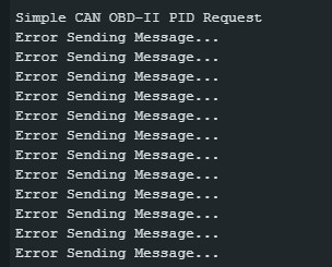 Serial output from Arduino showing CAN messages, potentially related to OBD2 and MCP2515 Arduino OBD2 project.
However, to properly interpret the engine speed, you need to understand the OBD2 response format for PID 0x0C. Typically, for PID 0x0C, the response data bytes will contain the engine speed value encoded across two bytes. You’ll need to parse these bytes according to the OBD2 standard to extract the RPM value. This usually involves combining the two bytes and applying a scaling factor.
For example, if you receive a response with data bytes 0x41 0x0C <byte A> <byte B> ..., where 0x41 indicates a positive response to service 01 and 0x0C is the PID, then bytes <byte A> and <byte B> contain the engine speed. The formula to calculate RPM is often:
RPM = ((byte A * 256) + byte B) / 4
You’ll need to implement this parsing logic in your Arduino code to extract and display the actual engine speed value in RPM.
Further Exploration and Project Expansion
This basic example provides a starting point for your MCP2515 Arduino OBD2 projects. You can expand this project in many ways:
- Requesting More PIDs: Explore the vast range of OBD2 PIDs and request other parameters like coolant temperature (PID 0x05), vehicle speed (PID 0x0D), and intake manifold pressure (PID 0x0B).
- Data Logging: Store the received OBD2 data to an SD card or send it wirelessly to a computer or smartphone for data logging and analysis.
- Real-time Dashboards: Create a custom dashboard using an LCD screen or a smartphone app to display real-time OBD2 data in a user-friendly format.
- Fault Code Reading: Implement functionality to read diagnostic trouble codes (DTCs) from your vehicle’s ECU to identify and troubleshoot potential issues.
By combining the power of Arduino, MCP2515, and OBD2, you can create a wide array of automotive diagnostic and monitoring tools. Start with this engine speed example and delve deeper into the world of vehicle data and customization!