Disclaimer: I am not a professional mechanic, just an enthusiast who successfully built this adapter. This guide is for informational purposes only. Follow these steps at your own risk. I am not responsible for any damage to your motorcycle, ECU, or any unforeseen consequences.
Tools You’ll Need
- Wire strippers/cutters
- Needle-nose pliers
- Molex crimping tool (optional, but recommended for a professional finish)
- Soldering iron and solder (recommended for enhanced connection reliability)
Parts List for Your Yamaha OBD2 Adapter
- 4-Pin Connector (Corsa Technic – 4-Pin Connector; suitable for 22-16AWG wire; insulation/seal size: 1.3-1.7mm)
- OBD-II Cable (Corsa Technic – OBD-II Cable)
Cost-Saving Tip: If you have spare automotive wire, you can purchase just the female OBD-II connector and wire the 4 necessary connections directly to the 4-pin connector. Ensure you select the correct 4-pin connector size compatible with your wire gauge.
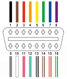
From the OBD-II connector (referred to as OBD2C), we will only utilize four essential wires for this Yamaha Obd2 Adapter project:
- Pin 4: Chassis Ground (Orange wire on OBD2C)
- Pin 6: CAN [J-2234] High (Green wire on OBD2C)
- Pin 14: CAN [J-2234] Low (Brown wire with white stripe on OBD2C)
- Pin 16: Battery Power (Green wire with white stripe on OBD2C)
Note: This guide is based on personal experience and is intended to be helpful. If you have suggestions for improvement, please feel free to create your own guide and share your expertise.
Step-by-Step Construction of Your Yamaha OBD2 Adapter
1) Preparing the OBD-II Cable Wires
It’s often recommended to twist CAN bus wire pairs to minimize electromagnetic interference. Begin by carefully removing the outer sheath and shielding from the OBD2C cable to access the internal wires. Identify and separate the four wires we need (Pins 4, 6, 14, and 16 as listed above). Bundle and secure the remaining twelve unused wires with a zip-tie to keep them organized and out of the way.
2) Preparing Wires for the 4-Pin Connector
A slight incompatibility exists with the chosen parts. The OBD2C wires are 26AWG, while the pins for the 4-pin connector (referred to as 4PC) are designed for 22AWG wires. To compensate for this difference in wire gauge, we’ll need to thicken the OBD2C wires.
The wires come pre-stripped with approximately 1/8″ of exposed wire. Carefully strip an additional 1/4″ to achieve about 3/8″ of exposed wire. Fold the exposed wire over itself and twist the strands together. This effectively doubles the wire thickness, making it a better fit for the 4PC pins.
Before proceeding, slide one of the provided rubber seals from the 4PC kit onto each of the four prepared wires. These seals will provide environmental protection at the connector.
3) Inserting Wires into 4-Pin Connector Pins
Examine the pins for the 4PC. You’ll notice two sets of prongs. The front prongs are designed to crimp onto the exposed wire, while the rear prongs crimp onto the wire insulation (over the rubber seal in this case).
Insert the prepared wire into the pin, ensuring the exposed wire aligns with the front set of prongs. The image below illustrates the size discrepancy between the thin wire and the larger pin connector. Due to the wire’s small gauge, using needle-nose pliers to hold the wire in place during the next step is highly recommended.
4) Soldering the Wires to the Connector Pins (Recommended)
Soldering provides a robust and electrically sound connection, which is particularly beneficial given the small gauge of the wires. While crimping is an alternative, soldering offers added security, especially when dealing with wires that are slightly undersized for the connector pins.
If you choose to solder, apply a small amount of solder to create a strong bond between the wire and the pin. If you’re new to soldering, numerous helpful tutorials are available online, such as this YouTube video on soldering techniques.
5) Crimping the Connector Pins (Alternative to Soldering)
If you possess a Molex crimping tool, this step is simplified. Position the pin and wire in the crimping tool and apply pressure to securely crimp the front prongs around the exposed wire.
For those without a specialized crimping tool, needle-nose pliers can be used. Carefully and gradually fold one of the front prongs over the wire using the pliers, working at an angle. Repeat this for the second prong, ensuring a tight crimp. This YouTube video demonstrates crimping techniques using pliers, which can be a helpful visual guide. For extra security, you can further compress the crimped prongs with pliers, though this might be considered excessive.
6) Crimping the Seal and Completing Pin Termination
Slide the rubber seal up the wire until it sits between the rear set of prongs on the 4PC pin. Employ the same crimping technique used in the previous step to fold these rear prongs over the rubber seal, securing it in place and providing strain relief and environmental sealing.
7) Twisting Wire Pairs for Noise Reduction
Although the exact reason isn’t definitively known, many DIY guides for similar adapters recommend twisting specific wire pairs. This practice is likely intended to further minimize electromagnetic interference, particularly on the CAN bus lines. Pair and twist the wires as follows:
- Pin 4 (Orange) / Pin 16 (Green w/white stripe) – Power and Ground pair
- Pin 6 (Green) / Pin 14 (Brown w/white stripe) – CAN bus High and Low pair
8) Assembling the 4-Pin Connector
Insert the terminated pins into the 4PC housing in the correct orientation as shown in the diagram below. It’s crucial to follow this pinout to ensure proper communication with your Yamaha motorcycle’s diagnostic system.
- Pin 14 (Brown w/white stripe) > Connector Slot A
- Pin 6 (Green) > Connector Slot B
- Pin 16 (Green w/white stripe) > Connector Slot C
- Pin 4 (Orange) > Connector Slot D
Push each pin into the rear of the connector housing until it clicks audibly, indicating it is securely locked in place. Using needle-nose pliers to gently pull on the wire from the rear can help seat and lock the pin fully.
Your Yamaha OBD2 Adapter is Complete!
This DIY Yamaha OBD2 adapter has been successfully tested to read and clear diagnostic trouble codes (DTCs) on compatible Yamaha motorcycles.
If any step in this guide is unclear, please ask for clarification, and I’ll do my best to provide further explanation or additional photos.