Are you struggling to get your Arduino CAN Bus Shield to communicate with your car’s OBD2 port? Many makers and car enthusiasts dive into projects needing real-time vehicle data, like engine RPM and speed, only to hit roadblocks. If you’re finding yourself in this situation, especially with a Seeed CAN Bus Shield V2.0, you’re not alone. This guide will walk you through common issues and troubleshooting steps to get your Arduino and CAN Bus Shield reading OBD2 data successfully.
The Frustration of Silence: No OBD2 Data
Imagine the excitement of building a custom instrument cluster, only to be met with silence when you connect your Arduino to your car. This is exactly the situation many face when trying to interface an Arduino CAN Bus Shield with the OBD2 port. You might be using example code, checking wiring diagrams, and still seeing no data coming through. It’s a common problem, and often fixable with systematic troubleshooting.
One user on an Arduino forum described this exact frustration. They were using a Seeed CAN Shield V2.0 and, despite trying various code examples and wiring configurations, couldn’t get any readings like engine RPM or vehicle speed. They even observed strange behavior on an oscilloscope, with the shield seemingly “spamming” messages continuously without receiving responses. Sound familiar?
Let’s break down the potential culprits and how to address them.
Diagnosing the Issue: Is Your CAN Bus Shield Really Talking?
Before diving deep into code and configurations, let’s address the fundamental question: is your CAN Bus Shield actually communicating at all? The user experiencing the issue used an oscilloscope and saw activity, but wasn’t sure if it was correct.
Here are a few things to consider:
-
Shield Functionality: If you only have one shield, it’s hard to definitively say if it’s working. However, seeing some signal on an oscilloscope is a good sign. The “spamming” behavior observed could be the shield repeatedly sending requests without receiving acknowledgements, which is plausible if communication isn’t correctly established.
-
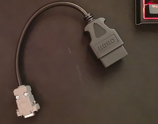
Wiring Woes: OBD2 wiring can be tricky. Even if you’ve checked diagrams multiple times, double-checking is crucial. The user in our example even created their own OBD2 to DB9 cable and tested it with a multimeter, which is excellent practice.
- CAN High and CAN Low: Ensure CAN High and CAN Low wires are correctly connected between your OBD2 cable, the CAN Bus Shield, and your car’s OBD2 port. Reversed wires are a common mistake.
- Ground and Power: Verify proper ground and power connections to the shield.
- Termination Resistor: Most CAN Bus systems require a 120Ω termination resistor at each end of the bus to prevent signal reflections. Some shields have this built-in (often with a jumper to enable/disable). Check your shield’s documentation to ensure termination is correctly handled.
-
CAN Bus Speed Mismatch: CAN Bus communication relies on a specific speed (baud rate). OBD2 typically uses 500 kbps. Ensure your Arduino code and CAN Bus Shield are configured for the correct speed. The provided code examples use
CAN_500KBPS, which is likely correct for OBD2.
Code Deep Dive: Are You Sending the Right Messages?
Even with correct wiring and a functional shield, the code you’re using is critical. Let’s examine the code snippets provided by the user and discuss common pitfalls.
Code Example 1 (Modified Seeed Studio Example):
#include <spi.h>
#include "mcp_can.h"

/*SAMD core*/
#ifdef ARDUINO_SAMD_VARIANT_COMPLIANCE
#define SERIAL SerialUSB
#else
#define SERIAL Serial
#endif

// the cs pin of the version after v1.1 is default to D9
// v0.9b and v1.0 is default D10
const int SPI_CS_PIN = 9;
MCP_CAN CAN(SPI_CS_PIN); // Set CS pin

#define MODE1_PID_ENGINE_RPM 0x0C
#define MODE1_PID_VEHICLE_SPEED 0x0D
#define MODE1_PID_COOLANT_TEMP 0x05

#define REQ_MSG 0x7DF
#define RESP_MSG 0x7E8

#define MODE1_CURRENT_DATA 0x01
#define STANDARD_FRAME 0
#define EXTENDED_FRAME 1
#define BYTE_UNUSED 0x55

void sendPid(unsigned char __pid) {
  const uint8_t DATA_LEN = 0x02;
  uint8_t data_buf[8] = { DATA_LEN, MODE1_CURRENT_DATA, __pid, BYTE_UNUSED, BYTE_UNUSED, BYTE_UNUSED, BYTE_UNUSED, BYTE_UNUSED};
  char serial_msg_buf[5];
  snprintf(serial_msg_buf, 5, "%02x", __pid);
  SERIAL.print("SEND PID: 0x");
  SERIAL.println(serial_msg_buf);
  const uint8_t MSG_LEN = 8;
  CAN.sendMsgBuf(REQ_MSG, STANDARD_FRAME, MSG_LEN, data_buf);
}

void setup() {
  SERIAL.begin(115200);
  while (CAN_OK != CAN.begin(CAN_500KBPS)) { // init can bus : baudrate = 500k
    SERIAL.println("CAN BUS Shield init fail");
    SERIAL.println(" Init CAN BUS Shield again");
    delay(100);
  }

  /* set mask, set both the mask to 0x3ff */
  CAN.init_Mask(0, 0, 0x7FC);
  CAN.init_Mask(1, 0, 0x7FC);

  /* set filter, we can receive id from 0x04 ~ 0x09 */
  CAN.init_Filt(0, 0, RESP_MSG);
  CAN.init_Filt(1, 0, RESP_MSG);
  CAN.init_Filt(2, 0, RESP_MSG);
  CAN.init_Filt(3, 0, RESP_MSG);
  CAN.init_Filt(4, 0, RESP_MSG);
  CAN.init_Filt(5, 0, RESP_MSG);

  SERIAL.println("CAN BUS Shield init ok!");
}

void loop() {
  sendPid(MODE1_PID_ENGINE_RPM);
  delay(5);
  taskCanRecv();
  delay(1000);
}

void taskCanRecv() {
  unsigned char len = 0;
  unsigned char buf[8];

  if (CAN_MSGAVAIL == CAN.checkReceive()) { // check if get data
    CAN.readMsgBuf(&len, buf);    // read data,  len: data length, buf: data buf

    SERIAL.println("rn------------------------------------------------------------------");
    SERIAL.print("Get Data From id: 0x");
    SERIAL.println(CAN.getCanId(), HEX);

    for (int i = 0; i < len; i++) {
      SERIAL.print(buf[i], HEX);
      SERIAL.print("t");
    }
    SERIAL.println();
  }
}
Key observations and potential issues:
- Library Inclusion: The code includes
mcp_can.h, which is the correct library for MCP2515 based CAN Bus Shields like the Seeed Studio one. Ensure you have this library installed in your Arduino IDE. - CS Pin Definition: The Chip Select (CS) pin for SPI communication is correctly defined as pin 9 (or potentially 10 for older shield versions – double-check your shield’s documentation!).
- CAN Bus Initialization: The
CAN.begin(CAN_500KBPS)function sets the baud rate. This is likely correct for OBD2. The code also includes error handling for initialization failure. - Filters and Masks: The code sets masks and filters to receive messages with ID
0x7E8(RESP_MSG). This is the standard response ID for OBD2 requests sent to0x7DF(REQ_MSG). Filters are important to reduce the load on the Arduino by only processing relevant messages. - PID Requests: The
sendPid()function correctly formats the CAN message to request a specific PID (Parameter ID). It sends a request for PID0x0C(Engine RPM) in theloop(). - Data Handling in
taskCanRecv(): This function checks for received messages and prints the ID and data bytes to the serial monitor.
Possible issues within the code:
- Delay after
sendPid(): Thedelay(5)after sending the PID request might be too short. The car’s ECU (Engine Control Unit) might need a little more time to process the request and send a response. Try increasing this delay. - Filtering Issues: While the filter is set to
0x7E8, there might be subtle issues with the mask configuration preventing responses from being received. Double-check the Seeed CAN Bus Shield library documentation and examples related to filtering. For initial testing, you could try temporarily disabling filters to see if any CAN messages are being received. However, be mindful that disabling filters can overload the Arduino if there’s a lot of CAN traffic. - PID Support: While
0x0C(Engine RPM) and0x0D(Vehicle Speed) are standard OBD2 PIDs, it’s possible your specific car doesn’t support them, or uses a slightly different implementation. While less likely, it’s something to consider if everything else seems correct. Using an OBD2 scanner to verify which PIDs are supported by your car is a good step.
Code Example 2 (YouTube Video Code):
#include <canbus.h>
#include <defaults.h>
#include <global.h>
#include <mcp2515.h>
#include <mcp2515_defs.h>
#include <wire.h>
#include "U8glib.h" // U8g setup
U8GLIB_SSD1306_128X64_2X u8g(U8G_I2C_OPT_NO_ACK | U8G_I2C_OPT_FAST);

const uint8_t N_CHARS_MAX = 15;
int rpm = 0;
char textBuf[N_CHARS_MAX];

void obd2Request() {
  tCAN message;
  message.id = 0x7DF;
  message.header.rtr = 0;
  message.header.length = 8;
  message.data[0] = 0x02;
  message.data[1] = 0x01;
  message.data[2] = 0x0C;
  message.data[3] = 0x55;
  message.data[4] = 0x55;
  message.data[5] = 0x55;
  message.data[6] = 0x55;
  message.data[7] = 0x55;
  mcp2515_bit_modify(CANCTRL, (1<<REQDIS), 0); //Enable reception
  mcp2515_send_message(&message);
}

void displayRPM(int rpm) {
  u8g.firstPage();
  do {
    u8g.setFont(u8g_font_6x10);
    u8g.drawStr( 0, 10, "Engine RPM");
    u8g.setFont(u8g_font_10x20);
    sprintf(textBuf, "%d RPM", rpm);
    u8g.drawStr( 0, 40, textBuf);
  } while ( u8g.nextPage() );
}


void setup() {
  SERIAL.begin(115200);
  u8g.setFont(u8g_font_unifont);

  if(mcp2515_init(CANSPEED_500KBPS,CANMASK_ALL,CANFILTER_ALL) == CAN_OK){
    SERIAL.println("MCP2515 Init OK!");
  }else{
    SERIAL.println("MCP2515 Init Fail...");
  }
}

void loop() {
  obd2Request();
  if(mcp2515_check_message()){
    tCAN message;
    mcp2515_read_message(&message);

    if(message.id == 0x7E8){
      int rpmCalc = ((message.data[3]*256) + message.data[4])/4;
      displayRPM(rpmCalc);
      SERIAL.print("RPM: ");
      SERIAL.println(rpmCalc);
      rpm = rpmCalc;
    }
  }
  delay(1000);
}
Key observations and potential issues:
- Different Library: This code uses a different CAN Bus library (
canbus.h,mcp2515.h, etc.). This library might have slightly different initialization and message handling functions compared to the Seeed Studio library. Ensure you are using the correct library and examples for your specific CAN Bus Shield if you are using this code. - OLED Display Integration: This code is designed to display RPM on an SSD1306 OLED display. This is a nice feature, but for initial troubleshooting, it might be simpler to focus on getting data to the serial monitor first, like in the first code example.
- MCP2515 Initialization: The
mcp2515_init()function is used to initialize the CAN controller. The parametersCANSPEED_500KBPS, CANMASK_ALL, CANFILTER_ALLsuggest it’s trying to set 500 kbps speed and disable filters initially (CANFILTER_ALLmight mean disable filtering in this library – check the library documentation). - Message Reception and RPM Calculation: The code checks for messages and specifically looks for messages with ID
0x7E8. If a message with this ID is received, it attempts to calculate RPM based on data bytes 3 and 4. The RPM calculation((message.data[3]*256) + message.data[4])/4is a standard formula for decoding RPM from OBD2 Mode 01 PID 0C.
Possible issues with this code:
- Library Compatibility: Ensure this library is fully compatible with your Seeed CAN Bus Shield V2.0. Library incompatibilities can cause subtle issues. It’s generally safer to start with examples specifically designed for your shield and library (like the Seeed Studio examples).
- Initialization Issues: While the code checks for initialization success, there might still be underlying configuration problems.
- Filtering (if
CANFILTER_ALLdoesn’t disable it): IfCANFILTER_ALLdoesn’t actually disable filtering in this library, it might be unintentionally filtering out the responses. - RPM Calculation Logic: While the RPM calculation formula is generally correct, there could be minor variations in how different ECUs report RPM. If you get some data but the RPM values are incorrect or nonsensical, this might be a point to investigate further.
Systematic Troubleshooting Steps: Getting Data Flowing
Here’s a structured approach to troubleshoot your Arduino Can Bus Shield Obd2 connection:
-
Verify Basic CAN Communication:
- Simple CAN Send/Receive Test: Before connecting to your car, try a basic CAN communication test between two CAN Bus Shields if possible. This will isolate whether the issue is with your shield itself or the OBD2 interface. If you only have one shield, skip to the next steps.
- Loopback Test (if shield supports it): Some CAN Bus Shields have a loopback mode (often enabled with a jumper). This allows you to send and receive messages on the same shield, verifying its basic functionality. Check your shield’s documentation for loopback test instructions.
-
Wiring – Triple Check Everything:
- OBD2 Cable: Re-examine your OBD2 cable wiring against multiple reliable diagrams. Ensure CAN High and CAN Low are correctly mapped.
- Shield Connections: Verify all connections between the CAN Bus Shield and your Arduino are secure and correct (SPI pins, power, ground).
- Termination Resistor: Confirm the 120Ω termination resistor is correctly configured (either built-in and enabled, or external if needed).
-
Code – Start Simple and Iterate:
- Seeed Studio Example Code: Begin with the most basic example code provided by Seeed Studio for their CAN Bus Shield (like the
OBDII_PIDsexample you initially tried). Simplify it even further if needed, just to send one basic OBD2 request (e.g., request for PID0x0CRPM). - Serial Monitor Debugging: Use
Serial.print()statements extensively to debug:- Confirm CAN Bus Shield initialization is successful.
- Print the CAN messages you are sending.
- Print any CAN messages you are receiving, regardless of ID, to see if anything is coming through at all.
- Baud Rate: Double-check that your code and shield are set to 500 kbps.
- Filtering (Initial Test – No Filtering): Temporarily comment out or disable any filtering in your code to see if you receive any CAN messages from the car. If you start receiving a flood of messages, then filtering is something to revisit later. If you still receive nothing, filtering is likely not the primary issue.
- Increase Delays: Increase the delays in your code, especially after sending a PID request (
delay(5)might be too short, trydelay(50)ordelay(100)). - PID Variations: Try requesting different standard OBD2 PIDs (e.g.,
0x0Dfor Vehicle Speed,0x05for Coolant Temperature) to see if any of them elicit a response.
- Seeed Studio Example Code: Begin with the most basic example code provided by Seeed Studio for their CAN Bus Shield (like the
-
OBD2 Port and Car Compatibility:
- OBD2 Scanner Verification: You’ve already confirmed your OBD2 port is working with a scanner, which is excellent. This rules out a completely dead OBD2 port.
- Car Protocol Variations: While OBD2 is a standard, there can be slight variations in implementation across different car makes and models. Less common, but possible.
-
Oscilloscope (Advanced):
- Signal Quality: If you have access to an oscilloscope, re-examine the CAN Bus signals. Are they clean and within expected voltage levels? Are you seeing CAN High and CAN Low signals that are differential? (CAN High goes high, CAN Low goes low for a dominant bit, and vice versa for a recessive bit). The image you provided shows some signal, but it’s hard to judge signal quality definitively from a static image.
- Message Timing: If you can decode the oscilloscope traces, try to verify the timing and structure of the CAN messages being sent by your shield.
Seeking Community Help
If you’ve gone through these steps and are still stuck, don’t hesitate to seek help from online communities and forums. Provide detailed information about your setup:
- Specific CAN Bus Shield Model: (Seeed CAN Bus Shield V2.0)
- Arduino Board: (e.g., Arduino Uno, Nano, etc.)
- Car Make, Model, and Year:
- OBD2 Cable Wiring Diagram (if custom-made):
- Code Snippets: (Post your code using code blocks for readability).
- Detailed Description of Symptoms: (What you’re seeing, what you’ve tried, oscilloscope readings if available).
- Images of your setup (wiring, connections):
The Arduino and car hacking communities are full of knowledgeable people who are often willing to assist. By systematically troubleshooting and clearly describing your problem, you’ll significantly increase your chances of finding a solution and getting your Arduino CAN Bus Shield communicating with your OBD2 port successfully.