Are you a car enthusiast or a DIY mechanic looking to delve into the world of vehicle diagnostics? One of the first steps is understanding and accessing your car’s On-Board Diagnostics II (OBD2) system. While there are many off-the-shelf OBD2 scanners, sometimes you might need a custom solution, or simply enjoy the hands-on approach of building your own tools. This guide will walk you through the process of creating your own OBD2 to USB cable, focusing on the essential pinout and wiring, so you can connect your car to your computer for diagnostics and data analysis.
Disclaimer: Before we begin, it’s crucial to understand that working with vehicle electronics involves risks. This guide is based on personal experience and is provided for informational purposes only. I am not an expert or a professional, and this is a DIY project. If you decide to follow these steps, you are doing so at your own risk. Incorrect wiring or handling of components could potentially damage your vehicle’s Electronic Control Unit (ECU) or other systems. Always double-check your connections and proceed with caution. We are not responsible for any damage or issues that may arise from attempting this project.
Understanding OBD2 and DIY Cables
OBD2 is a standardized system used in most modern vehicles to monitor and report on various vehicle parameters, from engine performance to emissions. Accessing this data can be incredibly useful for diagnosing problems, monitoring your car’s health, or even customizing performance.
While commercial OBD2 scanners are readily available, building your own cable offers several advantages:
- Cost-Effectiveness: Creating your own cable can be cheaper than buying a specialized scanner for basic connectivity.
- Customization: You can tailor the cable to your specific needs, length, and connector types.
- Learning Experience: It’s a fantastic way to learn about OBD2 systems, wiring, and basic automotive electronics.
- Direct Connection: For advanced users, a direct cable can sometimes offer a more reliable connection than wireless options for certain tasks.
This guide focuses on creating the cable itself, specifically the pinout configuration needed to connect the OBD2 port to a 4-pin connector, which can then be adapted to USB using readily available USB to serial adapters if needed for computer connectivity. This initial step is fundamental in creating a functional diagnostic link.
Parts and Tools You’ll Need
To build your OBD2 cable, gather the following tools and parts. Having everything ready before you start will make the process smoother and more efficient.
Tools:
- Wire Strippers/Cutters: Essential for preparing the wires by removing insulation without damaging the conductor.
- Needle-Nose Pliers: Very helpful for manipulating small components, holding wires in place, and crimping connector pins.
- Molex Crimping Tool (Recommended): While not strictly required, a crimping tool designed for Molex connectors (or similar pin connectors) will make a much more secure and professional connection. Using pliers can work, but crimping tools ensure proper and consistent pressure.
- Soldering Iron (Recommended): Soldering provides a robust and reliable electrical connection, especially for smaller gauge wires. It’s highly recommended for this project, though crimping alone might suffice if done very carefully.
Parts:
-
4-Pin Connector: This connector will interface with the wires from the OBD2 cable. Ensure it’s compatible with the wire gauge you’ll be using (22-16AWG is common and suitable for this application). Look for connectors with appropriate pin sizes and insulation seals.
- Example Part: 4-pin connector (or similar, ensure pin/wire size and insulation/seal size are compatible)
-
OBD-II Cable (with Female Connector): You’ll need an OBD2 cable that you can modify. You can purchase a complete OBD2 extension cable and cut off one end to access the internal wires.
- Example Part: OBD-II Cable (or similar extension cable)
-
Spare Wire (Optional): If you have suitable wire (22-16AWG) already available, you can save a bit by purchasing just the female OBD-II connector separately and wiring it directly to the 4-pin connector. However, using a pre-made OBD2 cable simplifies the process and ensures you have the correct OBD2 connector.
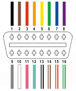
For this project, we will be utilizing only four essential wires from the 16 available in the OBD2 connector. These are crucial for basic CAN bus communication, which is the most common protocol for OBD2 diagnostics in modern vehicles. The specific pins and their functions are:
- Pin 4 (Chassis Ground): Provides a ground reference for the vehicle’s electrical system. (Typically an orange wire in the example OBD2 cable – OBD2C).
- Pin 6 (CAN [J-2284] High): Carries the CAN bus high signal for communication. (Typically a green wire in OBD2C).
- Pin 14 (CAN [J-2284] Low): Carries the CAN bus low signal for communication. (Typically a brown wire with a white stripe in OBD2C).
- Pin 16 (Battery Power): Provides 12V battery power to the OBD2 device. (Typically a green wire with a white stripe in OBD2C).
Step-by-Step Guide to Building Your OBD2 Cable
Now, let’s proceed with the step-by-step instructions to assemble your DIY OBD2 cable. Remember to work in a well-lit and organized space.
Step 1: Prepare the OBD2 Cable
- Isolate the Wires: Carefully cut open the outer sheath and shielding of the OBD2 cable to expose the internal wires. Be cautious not to damage the insulation of the inner wires.
- Separate the Four Essential Wires: Identify and separate the four wires we need: Pin 4 (orange), Pin 6 (green), Pin 14 (brown w/white stripe), and Pin 16 (green w/white stripe) from the OBD2 cable (OBD2C).
- Organize Remaining Wires: Group the remaining 12 wires and secure them out of the way using a zip tie or electrical tape. We won’t be using these for this basic cable.
Step 2: Prepare the Wires and 4-Pin Connector Pins
- Strip Wire Insulation: The wires in the OBD2 cable are often thin (26AWG in the example). The pins for the 4-pin connector (4PC) are designed for slightly thicker wires (22AWG). Carefully strip about 3/8″ of insulation from the end of each of the four selected wires.
- “Thicken” the Wires (If Necessary): Due to the gauge mismatch, to ensure a better fit in the 4-pin connector pins, fold the exposed wire strands back over themselves and twist them tightly. This effectively thickens the wire and improves contact within the pin.
- Slide on Rubber Seals: The 4-pin connector kit typically includes rubber seals. Slide one rubber seal onto each of the four prepared wires. These seals provide environmental protection to the connection once assembled.
Step 3: Soldering (or Crimping) the Wires to the Connector Pins
-
Position the Wire in the Pin: Insert the exposed wire into the 4-pin connector pin. The pin has two sets of prongs: one to crimp onto the wire conductor and another to crimp onto the insulation seal. Position the wire so it’s aligned with the front set of prongs (the ones closer to the pin tip).
-
Solder the Wire to the Pin (Recommended): If soldering, carefully apply solder to the area where the wire enters the pin. Ensure the solder flows and creates a solid mechanical and electrical connection. Be careful not to use excessive solder.
Soldering provides a more secure connection, especially with thinner wires. If you are new to soldering, practice on some scrap wire first. Numerous online resources and videos can teach you basic soldering techniques. -
Crimping the Pin (Alternative): If you have a crimping tool, position the pin and wire in the tool and crimp the front set of prongs firmly onto the wire. If you don’t have a crimping tool, you can carefully use needle-nose pliers to fold over the prongs onto the wire. However, crimping with pliers is less reliable and requires extra care to ensure a good connection.
Step 4: Secure the Seal and Assemble the 4-Pin Connector
-
Slide the Seal into Position: Slide the rubber seal up the wire until it sits between the rear set of prongs on the connector pin.
-
Crimp the Seal Prongs: Use the crimping tool or needle-nose pliers to fold the rear set of prongs over the rubber seal. This secures the seal and provides strain relief for the wire.
Step 5: Pinout and Final Assembly of the 4-Pin Connector
-
Wire Pairing (Recommended): It’s often recommended to twist pairs of wires, especially for CAN bus connections, to help reduce electromagnetic interference. Twist the following pairs together:
- Pin 4 (orange) with Pin 16 (green w/white stripe)
- Pin 6 (green) with Pin 14 (brown w/white stripe)
-
Insert Pins into 4-Pin Connector Housing: Refer to the pinout diagram below and insert the connector pins into the 4-pin connector housing in the correct orientation. You’ll be inserting the pins from the rear of the connector. You should hear a click when the pin locks into place. Use needle-nose pliers to gently pull on the wire from the back to ensure the pin is securely locked.
- Pin 14 (brown w/white stripe) > Connector Slot A
- Pin 6 (green) > Connector Slot B
- Pin 16 (green w/white stripe) > Connector Slot C
- Pin 4 (orange) > Connector Slot D
Testing Your DIY OBD2 Cable
Congratulations! You have now built your DIY OBD2 cable. To test it, you’ll need a compatible OBD2 diagnostic tool or software and a USB to serial adapter if you intend to connect it to a computer via USB.
- Connect the Cable: Plug the OBD2 connector end into your vehicle’s OBD2 port and the 4-pin connector end to your chosen adapter or diagnostic tool.
- Test Functionality: Use your diagnostic software or tool to attempt to connect to your vehicle’s ECU and read data or check for error codes.
Important Reminder: Always double-check your wiring and pinout before connecting your DIY cable to your vehicle. If you are unsure about any step, seek advice from experienced individuals or consult automotive electrical resources. Enjoy exploring the diagnostics of your vehicle with your homemade OBD2 cable!