The On-Board Diagnostic system, or OBD2, has become an indispensable tool for anyone involved with modern vehicles. From professional mechanics to car enthusiasts, understanding Obd2 Uses is key to unlocking a wealth of information about your vehicle’s health and performance. This guide provides a comprehensive look into the diverse applications of OBD2, going beyond basic diagnostics to reveal its full potential.
What is OBD2 and Why is it Important?
OBD2 is essentially your car’s internal health monitoring system. It’s a standardized protocol that allows access to diagnostic trouble codes (DTCs) and real-time data from your vehicle’s engine and other systems via a universal OBD2 connector.
Think of the check engine light on your dashboard. When this light illuminates, it’s your car signaling a problem. To understand what’s wrong, mechanics use an OBD2 scanner. This tool plugs into the 16-pin OBD2 connector, typically located under the dashboard near the steering wheel. The scanner sends “OBD2 requests” to the car’s computer, and the car responds with “OBD2 responses” containing valuable data like speed, engine temperature, fuel levels, and those crucial Diagnostic Trouble Codes (DTCs). This process dramatically speeds up troubleshooting and repair.
Understanding OBD2: The malfunction indicator light (MIL) signals issues that can be diagnosed using OBD2 tools.
Is OBD2 in My Car?
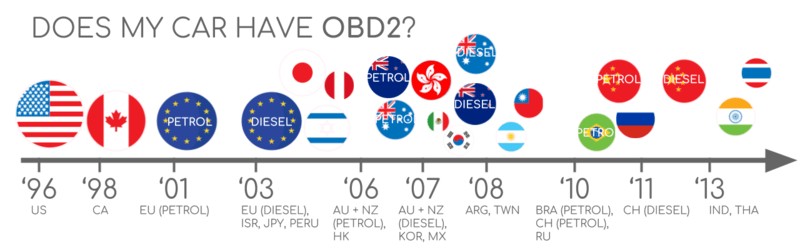
For most non-electric vehicles manufactured in recent decades, the answer is almost certainly yes. OBD2 compliance is widespread. While older cars might have a 16-pin connector, it’s not always a guarantee of OBD2 support. A key indicator is the vehicle’s origin and manufacturing date:
OBD2 Compliance Timeline: Check when and where your car was purchased new to determine OBD2 support.
A Brief History of OBD2 and Its Evolution
OBD2’s roots are in California, where the California Air Resources Board (CARB) mandated OBD systems in new cars from 1991 onwards for emission control.
The Society of Automotive Engineers (SAE) played a crucial role in standardizing OBD2, defining DTCs and the universal OBD connector (SAE J1962). The rollout of OBD2 was phased:
- 1996: OBD2 became mandatory in the USA for cars and light trucks.
- 2001: Required in the EU for gasoline cars.
- 2003: Extended to diesel cars in the EU (EOBD).
- 2005: OBD2 mandated in the US for medium-duty vehicles.
- 2008: US vehicles required to use ISO 15765-4 (CAN) as the foundation for OBD2 communication.
- 2010: OBD2 became mandatory for heavy-duty vehicles in the US.
OBD2 History: Originally for emission control, OBD2 has evolved and expanded its applications.
OBD2 Timeline: Key milestones in the development and mandating of OBD2 across different vehicle types and regions.
OBD3 and Future Trends: OBD2 is evolving towards remote diagnostics, cloud integration, and enhanced data access.
The Future of OBD2: Trends and Innovations
OBD2 is not static; it’s continuously evolving. Here are some significant trends shaping its future obd2 uses:
-
Challenges with Electric Vehicles (EVs): Interestingly, OBD2 as originally legislated for emission control doesn’t strictly apply to EVs. Many modern EVs don’t fully support standard OBD2 requests, opting instead for OEM-specific UDS communication. This can make accessing data from EVs more complex, requiring reverse engineering efforts, as seen in studies for brands like Tesla, Hyundai/Kia, Nissan, and VW/Skoda.
-
Modern OBD Alternatives: To address limitations in data richness and lower-layer protocols, alternatives like WWH-OBD (World Wide Harmonized OBD) and OBDonUDS (OBD on UDS) are emerging. These aim to improve OBD communication using the UDS protocol as a foundation. Learn more about UDS in our introduction to UDS.
-
OBD3 and Telematics: Manual emission checks are inefficient in today’s connected world. OBD3 proposes embedding telematics in vehicles. This involves adding a small radio transponder to transmit the vehicle identification number (VIN) and DTCs wirelessly to a central server for automated checks. Devices like the CANedge2 WiFi CAN logger and CANedge3 3G/4G CAN logger already facilitate data transfer via WiFi/cellular. While convenient and cost-saving, OBD3 raises privacy concerns.
-
Data Access Control: Initially for repair shops, OBD2 is now widely used by third parties for real-time data via OBD2 dongles and CAN loggers. However, the German car industry seeks to limit this, suggesting “turning off” OBD2 functionality during driving and centralizing data collection with manufacturers. They argue this is for security (reducing car hacking risks), but critics see it as a move to control ‘automotive big data’. This could significantly impact the market for third-party OBD2 services.
EV Data Access: Electric vehicles are presenting new challenges and potentially restricting open access to OBD2 data.
Deep Dive into OBD2 Standards
OBD2 operates as a higher-layer protocol, like a language built on a communication method (like a phone line). In the automotive context, CAN bus is the most common communication method for OBD2. This is similar to other CAN-based protocols like J1939, CANopen, and NMEA 2000.
OBD2 standards define the connector, lower-layer protocols, OBD2 parameter IDs (PIDs), and more. These standards can be categorized using the 7-layer OSI model, with both SAE (US standards) and ISO (EU standards) contributing. SAE J1979 and ISO 15031-5, as well as SAE J1962 and ISO 15031-3, are technically very similar, reflecting US and EU standardization efforts.
OBD2 and CAN bus in the OSI Model: Illustrating how OBD2 standards relate to the CAN bus protocol within the 7-layer OSI model.
The OBD2 Connector: Your Access Point [SAE J1962]
The 16-pin OBD2 connector, standardized by SAE J1962 / ISO 15031-3, is the physical interface for accessing your car’s data. The illustration below shows a Type A connector, also known as the Data Link Connector (DLC).
OBD2 Connector Pinout: Diagram of a Type A OBD2 connector, highlighting key pins and their functions.
Key features of the OBD2 connector:
- Usually located near the steering wheel, though sometimes hidden.
- Pin 16 provides battery power, even when the ignition is off.
- Pinout configuration varies depending on the communication protocol used.
- CAN bus, the most common protocol, uses pins 6 (CAN-H) and 14 (CAN-L).
OBD2 Connector Types: A vs. B
You’ll encounter both Type A and Type B OBD2 connectors. Type A is standard in cars, while Type B is more common in medium and heavy-duty vehicles.
While pinouts are similar, Type A provides 12V power, and Type B provides 24V. Baud rates often differ, with cars typically at 500K and heavy-duty vehicles often at 250K (though 500K support is increasing).
Type B connectors have a central interrupted groove, making a Type B OBD2 adapter cable compatible with both Type A and B sockets. However, a Type A adapter won’t fit into a Type B socket.
OBD2 Connector Types A and B: Comparison of Type A and Type B connectors, highlighting differences in power supply and typical vehicle applications.
OBD2 Communication and CAN Bus [ISO 15765-4]
Since 2008, CAN bus is the mandatory lower-layer protocol for OBD2 in US vehicles, as per ISO 15765.
ISO 15765-4 (Diagnostics over CAN or DoCAN) is a set of specifications applied to the CAN standard (ISO 11898), standardizing the CAN interface for diagnostic equipment, particularly at the physical, data link, and network layers:
- CAN bus bit-rate must be 250K or 500K.
- CAN IDs can be 11-bit or 29-bit.
- Specific CAN IDs are designated for OBD requests/responses.
- Diagnostic CAN frame data length is 8 bytes.
- OBD2 adapter cable length limit is 5 meters.
OBD2 and CAN bus: OBD2 utilizes CAN bus as its communication backbone, as defined by ISO 15765.
OBD2 CAN Identifiers (11-bit, 29-bit)
OBD2 communication relies on request and response messages.
Most cars use 11-bit CAN IDs for OBD2. ‘Functional Addressing’ uses ID 0x7DF, broadcasting requests to all OBD2-compliant ECUs. ‘Physical Addressing’ uses IDs 0x7E0-0x7E7 for specific ECU requests (less common).
ECUs respond with 11-bit IDs 0x7E8-0x7EF. 0x7E8 (ECM, Engine Control Module) and 0x7E9 (TCM, Transmission Control Module) are the most frequent response IDs.
Some vehicles, especially vans and medium/heavy-duty vehicles, use 29-bit CAN identifiers for OBD2. ‘Functional Addressing’ ID here is 0x18DB33F1. Responses use IDs 0x18DAF100 to 0x18DAF1FF (often 18DAF110 and 18DAF11E), sometimes seen as ‘J1939 PGN’ PGN 0xDA00 (55808), reserved for ISO 15765-2 in J1939-71.
OBD2 Request/Response Frames: OBD2 communication involves request frames sent to the vehicle and response frames containing the requested data.
OBD2 vs. OEM-Specific CAN Protocols
Crucially, car ECUs function using proprietary CAN protocols defined by the OEM, not OBD2. These protocols are brand, model, and year-specific. Without OEM documentation or reverse engineering, this data is generally inaccessible to third parties.
Connecting a CAN bus data logger to the OBD2 port might capture OEM-specific CAN data, typically broadcast at high rates (1000-2000 frames/second). However, newer cars often have a ‘gateway’ that blocks OEM data access via the OBD2 port, allowing only OBD2 communication.
Think of OBD2 as an additional, standardized protocol running alongside the OEM-specific protocol.
OBD2 vs. Proprietary CAN: OBD2 is a standardized layer on top of the OEM’s proprietary CAN bus communication.
Bit-Rate and ID Validation
OBD2 can use two bit-rates (250K, 500K) and two CAN ID lengths (11-bit, 29-bit), creating 4 possible combinations. Modern cars mostly use 500K and 11-bit IDs. Tools should systematically verify this.
ISO 15765-4 outlines an initialization sequence to determine the correct combination. This relies on the fact that OBD2-compliant vehicles must respond to a mandatory OBD2 request (see OBD2 PID section) and that incorrect bit-rates cause CAN error frames.
Newer ISO 15765-4 versions consider OBD communication via OBDonUDS versus OBDonEDS. This article primarily focuses on OBD2/OBDonEDS (OBD on emission diagnostic service per ISO 15031-5/SAE J1979) rather than WWH-OBD/OBDonUDS (OBD on Unified Diagnostic Service per ISO 14229, ISO 27145-3/SAE J1979-2).
To test for OBDonEDS vs. OBDonUDS, tools can send UDS requests with 11-bit/29-bit functional address IDs for service 0x22 and data identifier (DID) 0xF810 (protocol identification). OBDonUDS-supporting vehicles must have ECUs that respond.
OBDonEDS (OBD2, SAE OBD, EOBD, ISO OBD) is common in most non-EV cars, while WWH-OBD is mainly in EU trucks/buses.
OBD2 Bit-rate and CAN ID Validation Flowchart: A systematic process to identify the correct bit-rate and CAN ID configuration for OBD2 communication.
Five Lower-Layer OBD2 Protocols
While CAN (ISO 15765) is dominant today, older cars (pre-2008) might use other lower-layer protocols. Understanding these is useful when working with older vehicles.
- ISO 15765 (CAN bus): Mandatory in US since 2008, now widely used.
- ISO14230-4 (KWP2000): Common in 2003+ Asian cars.
- ISO 9141-2: Used in EU, Chrysler & Asian cars (2000-04).
- SAE J1850 (VPW): Mostly in older GM cars.
- SAE J1850 (PWM): Mostly in older Ford cars.
Five OBD2 Protocols: Overview of the five lower-layer protocols that have been used for OBD2 communication, including CAN bus and older standards.
ISO-TP: Transporting OBD2 Messages [ISO 15765-2]
OBD2 data is transmitted on CAN bus using ISO-TP (ISO 15765-2), a transport protocol enabling payloads larger than 8 bytes. This is essential for OBD2 functions like retrieving the Vehicle Identification Number (VIN) or Diagnostic Trouble Codes (DTCs). ISO 15765-2 handles segmentation, flow control, and reassembly. For more details, see our UDS introduction.
For data fitting within a single CAN frame, ISO 15765-2 uses ‘Single Frame’ (SF) format. The first data byte (PCI field) indicates payload length (excluding padding), leaving 7 bytes for OBD2 data.
ISO-TP Frame Types for OBD2: Different frame types used in ISO-TP for OBD2 communication, including Single Frame, First Frame, Consecutive Frame, and Flow Control Frame.
Decoding the OBD2 Diagnostic Message [SAE J1979, ISO 15031-5]
A raw ‘Single Frame’ OBD2 CAN message consists of an identifier, data length (PCI field), and data. The data itself is structured into Mode, parameter ID (PID), and data bytes.
OBD2 Message Structure: Breakdown of an OBD2 message, showing the Mode, Parameter ID (PID), and data bytes.
OBD2 Request/Response Example
Consider this example for requesting ‘Vehicle Speed’. The tool sends a request (CAN ID 0x7DF) with 2 payload bytes: Mode 0x01 and PID 0x0D. The car responds (CAN ID 0x7E8) with 3 payload bytes, including the speed value 0x32 (50 decimal) in the 4th byte. OBD2 PID 0x0D’s decoding rules indicate 50 km/h.
OBD2 Request and Response Example: Communication flow for requesting vehicle speed using OBD2 PIDs.
OBD2 PID 0D – Vehicle Speed: Details on PID 0D, used to request and decode vehicle speed data.
The 10 OBD2 Services (Modes)
OBD2 defines 10 diagnostic services or modes. Mode 0x01 provides real-time data, while others handle DTCs, freeze frame data, etc. Vehicles aren’t required to support all 10 modes and may have OEM-specific modes.
In OBD2 messages, the mode is in the 2nd byte. Requests use the mode directly (e.g., 0x01), while responses add 0x40 to the mode (e.g., 0x41).
OBD2 Services (Modes): Overview of the 10 standardized OBD2 diagnostic services, or modes.
OBD2 Parameter IDs (PIDs)
Each OBD2 mode includes Parameter IDs (PIDs). Mode 0x01, for example, has ~200 standardized PIDs for real-time data like speed, RPM, and fuel level. However, vehicles support only a subset of PIDs within a mode.
PID 0x00 in mode 0x01 is special. If an emissions-related ECU supports any OBD2 services, it must support mode 0x01 PID 0x00. Responding to PID 0x00, the ECU indicates support for PIDs 0x01-0x20. This makes PID 0x00 a fundamental OBD2 compatibility test. PIDs 0x20, 0x40, … , 0xC0 similarly indicate support for subsequent PID ranges in mode 0x01.
OBD2 PID Structure: PIDs are used within OBD2 modes to request specific parameters or data points.
OBD2 PID Overview Tool: Tools and resources are available to help understand and utilize OBD2 PIDs.
OBD2 PID Overview Tool
SAE J1979 and ISO 15031-5 appendices detail scaling information for standard OBD2 PIDs, enabling data decoding into physical values (as explained in our CAN bus intro).
Our OBD2 PID overview tool simplifies looking up mode 0x01 PIDs, constructing request frames, and dynamically decoding responses.
OBD2 PID overview tool
Practical Guide: Logging and Decoding OBD2 Data
Let’s illustrate how to log OBD2 data using the CANedge CAN bus data logger. The CANedge allows custom CAN frame transmission for OBD2 logging. Connect it to your vehicle using our OBD2-DB9 adapter cable.
OBD2 Data Logging Setup: Connecting an OBD2 data logger to a vehicle’s OBD2 port for data acquisition.
Testing Bit-rate: Validating the CAN bus bit-rate for OBD2 communication.
Supported PIDs Test: Reviewing responses to ‘Supported PIDs’ requests using software like asammdf.
Step #1: Bit-rate, ID, and Supported PID Validation
ISO 15765-4 guides determining the correct bit-rate and IDs. Test with CANedge as follows (see CANedge Intro for details):
- Send CAN frame at 500K; check success (else try 250K).
- Use the confirmed bit-rate for communication.
- Send ‘Supported PIDs’ requests; review results.
- Response IDs indicate 11-bit or 29-bit IDs.
- Response data reveals supported PIDs.
We provide plug-and-play configurations for these tests. Most post-2008 non-EV cars support 40-80 PIDs via 500K bit-rate, 11-bit CAN IDs, and OBD2/OBDonEDS.
As shown in the asammdf GUI screenshot, multiple responses to a single OBD request are common because the 0x7DF request ID polls all ECUs. Since all OBD2/OBDonEDS-compliant ECUs must support service 0x01 PID 0x00, many responses to this PID occur. Subsequent ‘Supported PIDs’ requests receive fewer ECU responses. The ECM ECU (0x7E8) often supports all PIDs supported by other ECUs, allowing reduced busload by directing subsequent requests to the ECM using ‘Physical Addressing’ CAN ID 0x7E0.
Step #2: Configuring OBD2 PID Requests
Having identified supported PIDs, bit-rate, and CAN IDs, configure your transmit list with desired PIDs. Consider:
- CAN IDs: Use ‘Physical Addressing’ request IDs (e.g., 0x7E0) to minimize multiple responses.
- Spacing: Add 300-500 ms between requests to prevent ECU overload.
- Battery Drain: Use triggers to stop transmissions when inactive.
- Filters: Filter for OBD2 responses if OEM-specific CAN data is also present.
With configuration complete, the device is ready to log raw OBD2 data!
CANedge OBD2 PID Requests: Example transmit list for requesting specific OBD2 PIDs using a CANedge data logger.
Decoded OBD2 Data Visualization: Visualizing decoded OBD2 data in asammdf, using a DBC file for interpretation.
Step #3: DBC Decoding of Raw OBD2 Data
To analyze and visualize logged data, decode raw OBD2 data into physical values (km/h, °C). Decoding information is in ISO 15031-5/SAE J1979 and online resources like Wikipedia. We offer a free OBD2 DBC file for easy DBC decoding in most CAN bus software.
OBD2 data decoding is more complex than standard CAN signals due to multiplexing. Different OBD2 PIDs share the same CAN ID (e.g., 0x7E8). Thus, CAN ID alone isn’t enough to identify signals. Decoding requires using CAN ID, OBD2 mode, and OBD2 PID. This ‘extended multiplexing’ is manageable in DBC files.
CANedge: Your OBD2 Data Logging Solution
The CANedge simplifies OBD2 data recording to an 8-32 GB SD card. Connect to a car/truck to start logging and decode data using free software/APIs and our OBD2 DBC.
OBD2 logger intro CANedge
OBD2 Multi-Frame Examples [ISO-TP]
While much OBD2 communication is single-frame, some operations use multi-frame communication via ISO-TP (ISO 15765-2). These require flow control frames (see UDS intro). CANedge configurations can use static flow control frames transmitted ~50 ms after the initial request. Multi-frame OBD2 responses need CAN software/API tools with ISO-TP support, like CANedge MF4 decoders.
OBD2 Multi-Frame Request Example: Requesting Vehicle Identification Number (VIN) using a multi-frame OBD2 request.
Example 1: Retrieving the Vehicle Identification Number (VIN)
The VIN is crucial for telematics, diagnostics, and more. Retrieve it via OBD2 using mode 0x09 and PID 0x02:
The tool sends a Single Frame request with PCI (0x02), service (0x09), and PID (0x02). The vehicle responds with a First Frame containing PCI, length (0x014 = 20 bytes), mode (0x49), and PID (0x02), followed by the Number Of Data Items (NODI) byte (0x01), and then the 17-byte VIN (HEX to ASCII conversion detailed in our UDS intro).
Example 2: Multi-PID Request (6x)
Tools can request up to 6 mode 0x01 PIDs in a single request frame. The ECU responds with data for supported PIDs (skipping unsupported ones), possibly across multiple frames via ISO-TP. This boosts data collection frequency but complicates signal encoding, making generic DBC files less useful. We advise against this method practically.
The multi-frame response is similar to the VIN example but includes requested PIDs and their data. PIDs are often ordered as requested. Decoding with DBC files is complex and not recommended practically, especially for generalized use across vehicles with varying PID support. Custom scripts interpreting request-response pairs are needed for robust handling at scale.
Example 3: Accessing Diagnostic Trouble Codes (DTCs)
Use OBD2 mode 0x03 (‘Show stored Diagnostic Trouble Codes’) to request emissions-related DTCs. No PID is needed in the request. ECUs respond with the number of stored DTCs (including 0 if none), each DTC being 2 bytes. Multi-frame responses are needed for more than 2 DTCs.
The 2-byte DTC value is split into category (first 2 bits) and a 4-digit hexadecimal code (remaining 14 bits), as per ISO 15031-5/ISO 15031-6. Decoded DTCs can be looked up using tools like repairpal.com.
OBD2 DTC Decoding: Example of decoding Diagnostic Trouble Codes (DTCs) from OBD2 data.
Real-World OBD2 Data Logging Use Cases
Obd2 uses extend across various applications for cars and light trucks:
OBD2 Data Logger Applications: OBD2 data logging has diverse applications in vehicle monitoring and diagnostics.
Car Data Logging
Obd2 uses in car data logging include reducing fuel consumption, improving driving habits, testing new parts, and insurance telematics.
obd2 logger
Real-time OBD2 Diagnostics: OBD2 interfaces enable real-time streaming of vehicle data for diagnostics.
Real-Time Vehicle Diagnostics
Obd2 uses interfaces to stream human-readable data in real-time, aiding in diagnosing vehicle problems efficiently.
obd2 streaming
OBD2 Predictive Maintenance: Utilizing OBD2 data for predictive maintenance and IoT applications.
Predictive Maintenance
IoT-connected OBD2 loggers monitor cars and light trucks in the cloud to predict and prevent breakdowns, leveraging obd2 uses for proactive vehicle management.
predictive maintenance
OBD2 as a Vehicle Black Box: OBD2 loggers can function as vehicle ‘black boxes’ for data recording and analysis.
Vehicle Black Box Logging
OBD2 loggers serve as ‘black boxes’ for vehicles, providing data for dispute resolution and detailed diagnostics, showcasing crucial obd2 uses in data recording.
can bus blackbox
Do you have an OBD2 data logging application in mind? Contact us for expert advice!
Explore our guides for more introductions, or download our comprehensive ‘Ultimate Guide’ PDF.
Ready to log or stream OBD2 data?
Get your OBD2 data logger today!
Buy now Contact us
Recommended for you
OBD2 DATA LOGGER: EASILY LOG & CONVERT OBD2 DATA
CANEDGE2 – PRO CAN IoT LOGGER
[