As a car owner or automotive professional, understanding your vehicle’s diagnostic system is crucial. The On-Board Diagnostics II (OBD2) system is the standard for vehicle self-diagnostics, and at the heart of this system is the 16 Pin Obd2 Pinout. This standardized connector is your gateway to a wealth of vehicle data, from engine performance to emissions control.
This guide, brought to you by the experts at obd2global.com, will provide a detailed look at the 16 pin OBD2 pinout. We’ll delve into its history, its role in modern vehicle diagnostics, and how understanding the pinout can empower you to troubleshoot issues, monitor performance, and much more. Whether you’re a seasoned mechanic or a curious car enthusiast, this comprehensive guide will enhance your understanding of the 16 pin OBD2 pinout and its significance in today’s automotive landscape.
What is OBD2 and Why is the 16 Pin OBD2 Pinout Important?
OBD2 is a vehicle’s built-in diagnostic system mandated in most modern cars. It’s designed to monitor the performance of major engine and emissions-related components. When something goes wrong, the OBD2 system generates diagnostic trouble codes (DTCs) and illuminates the malfunction indicator light (MIL), often known as the “check engine light,” on your dashboard.
To access this valuable diagnostic information, you need to connect to the vehicle’s OBD2 system through the standardized 16 pin OBD2 connector. This connector, typically located within reach of the driver’s seat, provides a universal interface for diagnostic tools to communicate with the vehicle’s electronic control units (ECUs). The 16 pin OBD2 pinout defines the function of each pin within this connector, ensuring compatibility and standardized communication across different vehicle makes and models.
Think of the 16 pin OBD2 pinout as a universal language interface for your car. Just as a USB port allows various devices to connect and communicate with a computer, the 16 pin OBD2 pinout enables diagnostic scanners, data loggers, and other tools to interface with your vehicle’s internal systems. Understanding this pinout is the first step in unlocking the potential of OBD2 diagnostics.
Understanding OBD2: The malfunction indicator light alerts you to potential issues detectable via the 16 pin OBD2 pinout.
A Brief History of OBD2 and the Standardization of the 16 Pin Connector
The journey to the standardized 16 pin OBD2 pinout began in California, driven by the California Air Resources Board (CARB). In the early 1990s, CARB mandated OBD systems in new vehicles for emissions monitoring. This initial OBD system, however, lacked standardization, leading to variations in connectors and communication protocols across manufacturers.
Recognizing the need for uniformity, the Society of Automotive Engineers (SAE) stepped in to standardize the system. This led to the development of OBD2, which included a standardized 16 pin OBD2 connector defined by SAE J1962 and ISO 15031-3. This standardization was a game-changer for the automotive industry, making vehicle diagnostics more accessible and efficient.
The rollout of OBD2 and the 16 pin OBD2 pinout was phased in over time:
- 1996: OBD2 became mandatory in the USA for cars and light trucks.
- 2001: Required in the EU for gasoline cars (EOBD).
- 2003: Required in the EU for diesel cars (EOBD).
- 2008: US vehicles mandated to use ISO 15765-4 (CAN) as the OBD2 communication basis.
This progressive implementation ensured that by the late 2000s, the 16 pin OBD2 pinout and the OBD2 protocol were globally recognized standards for vehicle diagnostics, significantly simplifying automotive repair and maintenance.
OBD2 Compliance Timeline: Check when and where your car was bought new to determine OBD2 support and the presence of a 16 pin OBD2 connector.
Delving Deep into the 16 Pin OBD2 Pinout: Pin by Pin Functionality
The 16 pin OBD2 pinout is not just a random arrangement of pins; each pin is assigned a specific function crucial for communication and power supply. Understanding these functions is key to correctly using OBD2 diagnostic tools and interpreting communication signals.
Here’s a detailed breakdown of the standard 16 pin OBD2 pinout (Type A):
| Pin Number | Pin Name | Function |
|---|---|---|
| 1 | Manufacturer Discretionary | Often undefined or manufacturer-specific; may be used for OEM-specific diagnostics. |
| 2 | SAE J1850 Bus+ | Positive line for SAE J1850 PWM and VPW communication protocols (older vehicles). |
| 3 | Manufacturer Discretionary | Often undefined or manufacturer-specific; may be used for OEM-specific diagnostics. |
| 4 | Chassis Ground | Ground connection for the vehicle chassis. |
| 5 | Signal Ground | Signal ground reference for communication signals. |
| 6 | CAN High (CAN-H) | High-level signal line for CAN bus communication (dominant protocol in modern vehicles). |
| 7 | ISO 9141-2 K-Line | K-Line for ISO 9141-2 and ISO 14230-4 (KWP2000) communication protocols (older vehicles). |
| 8 | Manufacturer Discretionary | Often undefined or manufacturer-specific; may be used for OEM-specific diagnostics. |
| 9 | Manufacturer Discretionary | Often undefined or manufacturer-specific; may be used for OEM-specific diagnostics. |
| 10 | SAE J1850 Bus- | Negative line for SAE J1850 PWM and VPW communication protocols (older vehicles). |
| 11 | Manufacturer Discretionary | Often undefined or manufacturer-specific; may be used for OEM-specific diagnostics. |
| 12 | Manufacturer Discretionary | Often undefined or manufacturer-specific; may be used for OEM-specific diagnostics. |
| 13 | Manufacturer Discretionary | Often undefined or manufacturer-specific; may be used for OEM-specific diagnostics. |
| 14 | CAN Low (CAN-L) | Low-level signal line for CAN bus communication. |
| 15 | ISO 9141-2 L-Line | L-Line for ISO 9141-2 and ISO 14230-4 (KWP2000) communication protocols (older vehicles). |
| 16 | Battery Power | Provides battery voltage (typically 12V for Type A) to the diagnostic tool. |

Key Pin Functions Explained:
- Power (Pin 16) and Ground (Pins 4 & 5): Pin 16 provides power to your OBD2 scan tool, while pins 4 and 5 establish ground connections. This power supply is essential for the operation of most diagnostic devices.
- CAN Bus (Pins 6 & 14): Pins 6 (CAN-H) and 14 (CAN-L) are the cornerstone of modern OBD2 communication. The Controller Area Network (CAN) bus is the dominant protocol for in-vehicle communication, including OBD2 diagnostics in most vehicles manufactured after 2008.
- J1850 Bus (Pins 2 & 10): Pins 2 (J1850 Bus+) and 10 (J1850 Bus-) were used for the SAE J1850 VPW and PWM protocols, primarily found in older GM and Ford vehicles.
- ISO 9141-2 / KWP2000 (Pins 7 & 15): Pins 7 (K-Line) and 15 (L-Line) were used for ISO 9141-2 and KWP2000 protocols, common in European and Asian vehicles from the late 1990s to early 2000s.
- Manufacturer Discretionary Pins (1, 3, 8, 9, 11, 12, 13): These pins are reserved for manufacturer-specific uses. They may be used for OEM-specific diagnostic protocols or other proprietary functions. Their function can vary widely between vehicle manufacturers.
Understanding the function of each pin within the 16 pin OBD2 pinout is critical for ensuring proper connection and communication with your vehicle’s diagnostic system. Incorrect connections can lead to communication errors or even damage to your diagnostic tool or vehicle’s electronics.
The 16 Pin OBD2 Pinout (Type A): A detailed diagram illustrating the function of each pin in the standard OBD2 connector.
OBD2 Connector Types: Type A vs. Type B and the 16 Pin Pinout Variations
While the 16 pin OBD2 pinout is largely standardized, there are variations to be aware of, primarily between Type A and Type B connectors. Type A is most commonly found in cars and light-duty vehicles, while Type B is more prevalent in medium and heavy-duty vehicles.
The key difference between Type A and Type B 16 pin OBD2 pinouts lies in the power supply pin (Pin 16):
- Type A: Pin 16 typically provides 12V power, suitable for most car diagnostic tools.
- Type B: Pin 16 typically provides 24V power, catering to the higher voltage systems in trucks and buses.
While the communication pins (CAN, J1850, ISO 9141-2) remain consistent in their pin assignments between Type A and Type B 16 pin OBD2 pinouts, the voltage difference is crucial. Using a Type A tool on a Type B vehicle (or vice-versa) without proper voltage adaptation can damage the tool or the vehicle’s electrical system.
Visually, you can distinguish between Type A and Type B 16 pin OBD2 connectors by an interrupted groove in the middle of the Type B connector. This mechanical difference also ensures that a Type A connector cannot be accidentally plugged into a Type B socket, preventing potential voltage mismatches. However, a Type B adapter cable is often designed to be compatible with both Type A and Type B sockets.
OBD2 Connector Types: Type A (12V) and Type B (24V) 16 pin OBD2 pinouts cater to different vehicle voltage systems.
OBD2 Protocols and the 16 Pin OBD2 Pinout: Connecting Communication Standards
The 16 pin OBD2 pinout supports several communication protocols, although modern vehicles primarily utilize the CAN bus protocol via pins 6 and 14. Understanding these protocols and their pin assignments within the 16 pin OBD2 pinout is important for diagnosing older vehicles or when working with protocol-specific diagnostic tools.
Here’s a recap of the primary OBD2 protocols and their associated pins in the 16 pin OBD2 pinout:
- CAN Bus (ISO 15765): Pins 6 (CAN-H) and 14 (CAN-L). The dominant protocol in modern vehicles (post-2008).
- KWP2000 (ISO 14230-4): Pin 7 (K-Line) and optionally Pin 15 (L-Line). Keyword Protocol 2000, used in many vehicles from the early 2000s.
- ISO 9141-2: Pin 7 (K-Line) and Pin 15 (L-Line). Similar to KWP2000, used in some European and Asian vehicles.
- SAE J1850 VPW: Pin 2 (J1850 Bus+). Variable Pulse Width Modulation, used primarily in older GM vehicles.
- SAE J1850 PWM: Pins 2 (J1850 Bus+) and 10 (J1850 Bus-). Pulse Width Modulation, used primarily in older Ford vehicles.
While CAN bus is now the mandated standard, older vehicles may utilize one of the other protocols. Diagnostic tools often need to automatically detect the protocol being used by the vehicle through the 16 pin OBD2 pinout to establish proper communication. In some cases, manual protocol selection might be required, especially when dealing with older or non-standard compliant vehicles.
OBD2 Protocol Standards: The 16 pin OBD2 pinout accommodates various communication protocols, with CAN bus being the modern standard.
Practical Applications: Using the 16 Pin OBD2 Pinout for Diagnostics and Data Logging
The 16 pin OBD2 pinout is your access point for a wide range of automotive diagnostic and data logging applications. By connecting a compatible tool to this connector, you can perform tasks such as:
- Reading Diagnostic Trouble Codes (DTCs): Identify the source of vehicle problems indicated by the check engine light.
- Clearing DTCs: Reset the check engine light after repairs are made.
- Viewing Live Data: Monitor real-time parameters like engine speed (RPM), coolant temperature, vehicle speed, and sensor readings.
- Performing Emission Tests: Check vehicle emissions compliance.
- Retrieving Vehicle Information: Obtain VIN and other vehicle-specific data.
- Data Logging: Record vehicle parameters over time for performance analysis or troubleshooting.
- Custom Parameter Identification (PIDs) Requests: Access specific data points beyond the standard OBD2 parameters, depending on vehicle support.
For mechanics, the 16 pin OBD2 pinout is an indispensable tool for efficient and accurate vehicle diagnostics. For car enthusiasts and researchers, it provides a gateway to understanding vehicle performance and behavior in detail.
To effectively utilize the 16 pin OBD2 pinout, you’ll need compatible hardware and software. This can range from simple handheld OBD2 scanners for basic DTC reading to advanced PC-based diagnostic systems and sophisticated data loggers for in-depth analysis. Understanding the 16 pin OBD2 pinout and the communication protocols it supports will help you choose the right tools for your specific needs.
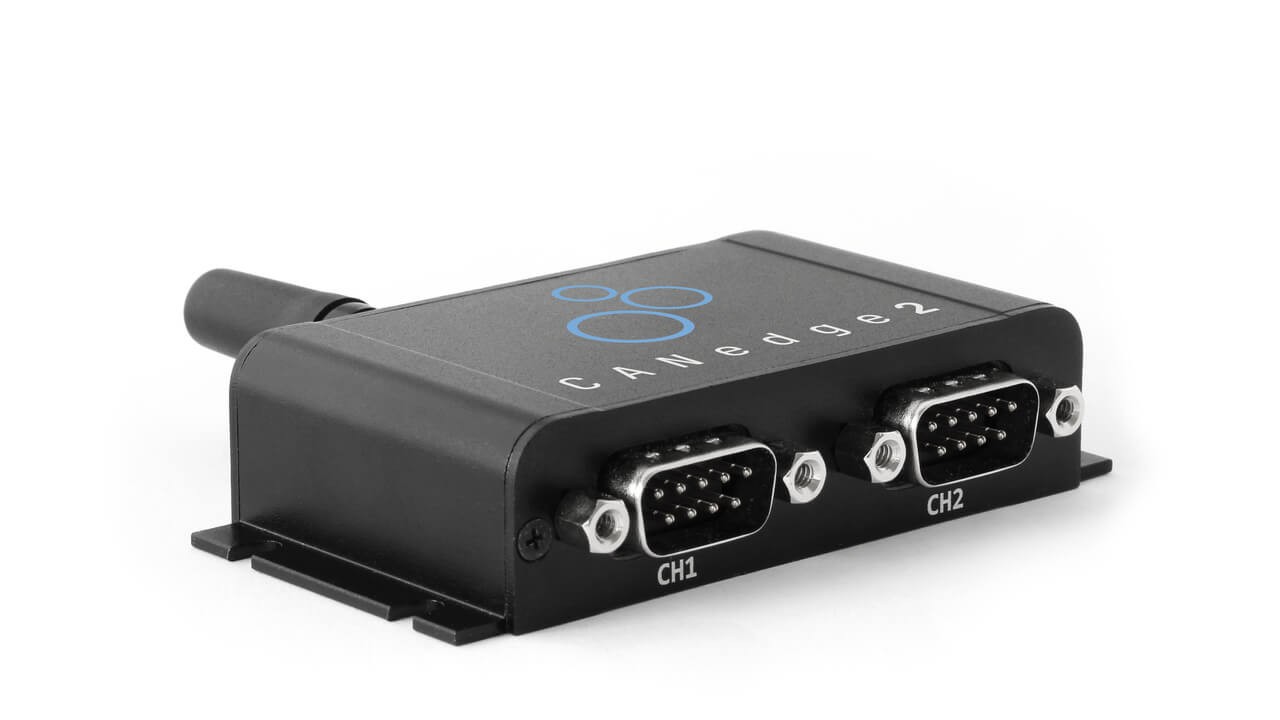
OBD2 Data Logging: Connecting a data logger to the 16 pin OBD2 pinout allows for recording vehicle parameters for analysis.
Future Trends and the 16 Pin OBD2 Pinout: Adapting to Automotive Evolution
While the 16 pin OBD2 pinout has been a cornerstone of automotive diagnostics for decades, the automotive landscape is constantly evolving. Trends like electric vehicles (EVs), advanced driver-assistance systems (ADAS), and increasing cybersecurity concerns are shaping the future of vehicle diagnostics and the role of the 16 pin OBD2 pinout.
- Electric Vehicles and OBD2: Current OBD2 standards are primarily geared towards internal combustion engine vehicles and emissions control. EVs, with their different powertrain architectures, often have limited OBD2 support or utilize OEM-specific diagnostic protocols. The future may see adaptations or new standards for EV diagnostics through the 16 pin OBD2 pinout or potentially new connector interfaces.
- OBD3 and Telematics: The concept of OBD3 envisions incorporating telematics capabilities into vehicles, enabling remote diagnostics and emissions monitoring. While the 16 pin OBD2 pinout might remain the physical interface, the communication protocols and data transmitted could expand significantly to support these telematics functions.
- Cybersecurity: As vehicles become increasingly connected, cybersecurity is a growing concern. The 16 pin OBD2 pinout, as a direct access point to vehicle systems, could be a potential vulnerability. Future standards and implementations may incorporate security measures to protect vehicle networks while maintaining diagnostic accessibility through the 16 pin OBD2 pinout.
Despite these evolving trends, the 16 pin OBD2 pinout is likely to remain a relevant interface for vehicle diagnostics for the foreseeable future. Its standardization and widespread adoption provide a solid foundation that can be adapted and expanded upon to meet the challenges of next-generation vehicles.
The Future of OBD2: While electric vehicles present new challenges, the 16 pin OBD2 pinout may adapt to remain relevant in vehicle diagnostics.
Conclusion: Mastering the 16 Pin OBD2 Pinout for Automotive Expertise
The 16 pin OBD2 pinout is more than just a connector; it’s a gateway to understanding your vehicle’s inner workings. From its origins in emissions control to its current role in comprehensive vehicle diagnostics, the 16 pin OBD2 pinout has become an essential interface for automotive professionals and enthusiasts alike.
By understanding the function of each pin, the protocols it supports, and its applications in diagnostics and data logging, you can unlock the full potential of the OBD2 system. As the automotive world continues to advance, a solid grasp of the 16 pin OBD2 pinout will remain a valuable asset for anyone involved in vehicle maintenance, repair, or performance analysis.
At obd2global.com, we are committed to providing you with the knowledge and tools you need to master automotive diagnostics. Explore our resources, guides, and products to further enhance your expertise in OBD2 and the 16 pin OBD2 pinout.
Ready to delve deeper into OBD2?
Explore our OBD2 Data Loggers
Learn more about CAN Bus and OBD2 Communication
Contact our Experts for OBD2 Solutions
Recommended for you
OBD2 DATA LOGGER: EASILY LOG & CONVERT OBD2 DATA
CANEDGE2 – PRO CAN IoT LOGGER
[