Want to tap into your Yamaha motorcycle’s diagnostics using a standard OBD2 scanner? While Yamaha uses a proprietary 4-pin diagnostic connector on many of their bikes, it’s possible to create a simple adapter cable to bridge this gap to the universally accepted OBD2 standard. This guide will walk you through the process of building your own Yamaha 4 Pin To Obd2 Cable, allowing you to read error codes, monitor engine parameters, and potentially perform other diagnostic functions on your Yamaha motorcycle.
Disclaimer: Before we begin, it’s important to understand that this is a DIY project. I am not a professional mechanic, and this guide is based on my personal experience. While this method worked for me, successfully building and using this cable is at your own risk. Incorrect wiring could potentially damage your motorcycle’s ECU or your diagnostic equipment. Proceed with caution and double-check all connections.
Tools and Parts You’ll Need to Build Your Yamaha 4 Pin to OBD2 Cable
To create your yamaha 4 pin to obd2 cable, you’ll need a few basic tools and readily available parts. Here’s a list of what you’ll need:
- Wire strippers/cutters
- Needle-nose pliers
- Molex crimping tool (recommended for professional results, but pliers can be used)
- Soldering iron and solder (recommended for a more secure connection)
- 4-Pin Connector (Corsa Technic – 4-Pin Connector – Pin/wire size = 22-16AWG; insulation/seal size = 1.3-1.7mm)
- OBD-II Cable (Corsa Technic – OBD-II Cable)
If you prefer, you can also source a female OBD-II connector separately and use your own wires, which can save a bit of cost. Just ensure you have suitable wire and the correct 4-pin connector to match your wire gauge.
Understanding the Wiring for Your Yamaha 4 Pin to OBD2 Cable
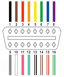
The OBD-II connector (OBD2C) has 16 pins, but for this yamaha 4 pin to obd2 cable, we only need to utilize four specific wires. These wires correspond to the essential signals required for basic diagnostics:
- Pin 4 (Chassis Ground): This is the ground connection, typically an orange wire on the specified OBD2 cable.
- Pin 6 (CAN [J-2234] High): This carries the CAN bus high signal, usually a green wire on the OBD2 cable. CAN bus is the communication protocol used in many modern vehicles, including Yamaha motorcycles, for diagnostics.
- Pin 14 (CAN [J-2234] Low): This carries the CAN bus low signal, often a brown wire with a white stripe on the OBD2 cable.
- Pin 16 (Battery Power): This provides power to the OBD2 scanner, generally a green wire with a white stripe on the OBD2 cable.
Step-by-Step Guide to Building Your Yamaha 4 Pin to OBD2 Cable
Let’s get started on assembling your yamaha 4 pin to obd2 cable. Follow these steps carefully:
1. Prepare the OBD-II Cable Wires:
Begin by separating the four wires you’ll be using from the OBD-II cable. Carefully remove the outer sheath and shielding to access the individual wires. Isolate the wires for pins 4, 6, 14, and 16 as described above. You can use a zip tie to neatly bundle the remaining unused wires and keep them out of the way.
2. Prepare the Wire Ends for the 4-Pin Connector:
The wires in the OBD2 cable are quite thin (26AWG), while the pins for the 4-pin connector (4PC) are designed for slightly thicker wires (22AWG). To ensure a good connection, we need to thicken the wire ends. Strip about 3/8″ of insulation from the end of each of the four wires. Then, fold the exposed wire strands back over themselves and twist them tightly. This will effectively double the wire thickness and make it a better fit for the connector pins. Slide a rubber seal from the 4PC kit onto each wire.
3. Attach Wires to 4-Pin Connector Pins:
Take one pin for the 4-pin connector. You’ll notice it has two sets of prongs. The inner set is for crimping onto the wire, and the outer set is for the rubber seal. Insert the prepared wire end into the pin, ensuring it aligns with the inner prongs. The wire might seem small compared to the pin; using needle-nose pliers to hold the wire in place can be helpful for the next step.
4. Soldering (Recommended) or Crimping the Wire to the Pin:
Soldering (Recommended): For a robust and reliable connection, soldering is highly recommended, especially given the thin wires. Solder the wire to the pin connector. Ensure the solder joint is solid. If you’re new to soldering, numerous helpful tutorials are available online, such as this YouTube video for soldering tips.
Crimping (Alternative): If you have a Molex crimping tool, use it to crimp the inner prongs of the pin connector securely around the wire. If you don’t have this tool, you can carefully use needle-nose pliers. Fold one prong at a time over the wire, using the pliers at an angle to apply pressure. This YouTube video provides guidance on crimping without a dedicated tool. For added security, you can use pliers to further flatten the crimped prongs.
5. Crimp the Seal Prongs:
Slide the rubber seal up the wire until it sits between the outer prongs of the pin connector. Use the same crimping technique (either with a crimping tool or needle-nose pliers) to fold these outer prongs over the rubber seal, securing it in place and providing strain relief and environmental protection.
6. Pair and Twist Wires (Recommended):
While not strictly necessary, it’s good practice to pair and twist the wires. This is often recommended in similar DIY cable builds to help reduce electromagnetic interference and improve signal integrity, especially for CAN bus signals. Pair the wires as follows:
- Pin 4 (orange) / Pin 16 (green w/white stripe) – Power and Ground
- Pin 6 (green) / Pin 14 (brown w/white stripe) – CAN High and CAN Low
Twist each pair of wires together.
7. Insert Pins into 4-Pin Connector Housing:
Finally, insert the completed pins into the 4-pin connector housing in the correct orientation as shown below:
- Slot A: Pin 14 (brown w/white stripe) – CAN Low
- Slot B: Pin 6 (green) – CAN High
- Slot C: Pin 16 (green w/white stripe) – Battery Power
- Slot D: Pin 4 (orange) – Chassis Ground
Push each pin into the rear of the connector housing until you hear a click, indicating it is locked securely in place. Using needle-nose pliers to gently pull the wire from the front can help seat the pin fully.
Testing Your DIY Yamaha 4 Pin to OBD2 Cable
Congratulations! You have now built your yamaha 4 pin to obd2 cable.
Now, it’s time to test it. Connect your DIY cable to your Yamaha motorcycle’s 4-pin diagnostic port and plug the OBD2 end into your OBD2 scanner. Power on your motorcycle and scanner. You should now be able to communicate with your bike’s ECU, read diagnostic trouble codes (DTCs), and view live data.
Important Note: Always double-check your wiring before connecting to your motorcycle. If you encounter any issues or are unsure about any step, re-examine your connections and consult online resources or seek advice from experienced individuals.
By following these steps, you can create your own yamaha 4 pin to obd2 cable and gain access to your Yamaha motorcycle’s diagnostic system, empowering you to understand and maintain your bike more effectively.