Are you fascinated by the data flowing beneath the hood of your car? The On-Board Diagnostics II (OBD2) system is a treasure trove of real-time information about your vehicle’s performance. By combining the power of an Arduino microcontroller with an MCP2515 CAN bus controller, you can tap into this data stream and create your own custom car diagnostics and monitoring tools. This guide will walk you through the basics of using the MCP2515 with Arduino to request and interpret OBD2 data, specifically focusing on retrieving engine speed (RPM).
Understanding OBD2, CAN Bus, and MCP2515
Modern vehicles use a Controller Area Network (CAN bus) to allow various electronic control units (ECUs) to communicate with each other. OBD2 is a standardized system that utilizes the CAN bus to provide diagnostic information. This information is accessed through Parameter IDs (PIDs), which are codes used to request specific data points, such as engine speed, coolant temperature, and more.
The MCP2515 is a standalone CAN controller that interfaces with microcontrollers like Arduino via SPI. It allows your Arduino to communicate on the CAN bus, sending requests for OBD2 data and receiving responses from your car’s ECU.
Setting Up Your Arduino with MCP2515 for OBD2
To get started, you’ll need the following hardware:
- Arduino board (Uno, Nano, etc.)
- MCP2515 CAN bus module
- OBD2 connector (to interface with your car)
- Wiring to connect the MCP2515 to your Arduino and OBD2 connector
For this guide, we’ll focus on the software aspect and understanding the code. Let’s examine an Arduino sketch designed to request engine speed data using the MCP2515.
Analyzing the Arduino Code for OBD2 PID Request
Below is a modified version of the code snippet provided, designed to request PID 0C (Engine Speed) and demonstrate basic OBD2 data retrieval using the MCP2515 and Arduino.
Code Breakdown:
- Includes:
mcp_can.hlibrary for MCP2515 communication andSPI.hfor SPI communication. - Definitions:
standard: Set to0for Extended CAN IDs, common in OBD2.LISTEN_ID,REPLY_ID,FUNCTIONAL_ID: CAN IDs for OBD2 communication.FUNCTIONAL_ID(0x7DF in standard 11-bit, 0x98DB33F1 in extended in this example) is used for broadcasting requests to all ECUs.txData[]: This is the crucial part. It defines the OBD2 request message.0x02: Indicates the number of bytes following are data bytes (Service + PID).0x01: OBD2 Service01– “Show current data”. This service is used to request real-time data.0x0C: The PID for Engine Speed (RPM).0x00, 0x00, 0x00, 0x00, 0x00: Padding bytes, often filled with0x00or0x55.
setup()function:- Initializes serial communication for debugging.
- Initializes the MCP2515 module, setting the CAN bus speed to 500kbps (standard for OBD2) and the clock to 8MHz.
- Configures CAN filters and masks to accept all Extended IDs in this example for simplicity. In a real-world application, you might want to refine these for security and efficiency.
- Sets the MCP2515 to normal operating mode.
- Configures the interrupt pin.
- Prints a message to the serial monitor.
loop()function:- Receiving CAN Messages: Checks for interrupt from MCP2515 indicating a received message. If a message is received, it reads the message buffer (
CAN0.readMsgBuf()) and prints the raw CAN data (ID, DLC, and data bytes) to the serial monitor. This is helpful for observing all CAN traffic, not just responses to our requests. - Sending OBD2 Request: Every 1000 milliseconds (1 second), it sends the
txData(Engine Speed PID request) usingCAN0.sendMsgBuf()to theFUNCTIONAL_ID. A message is printed to the serial monitor confirming if the message was sent successfully or not.
- Receiving CAN Messages: Checks for interrupt from MCP2515 indicating a received message. If a message is received, it reads the message buffer (
Interpreting the Engine Speed Response
After uploading this code to your Arduino and connecting it to your car’s OBD2 port (with proper MCP2515 wiring), open the serial monitor. You should see “Engine Speed Request Message Sent!” printed every second, and you’ll also see a stream of CAN messages being received.
To find the engine speed data, you need to look for responses to your request. OBD2 responses typically follow a specific format. For PID 0C (Engine Speed), the response data usually looks like this:
03 41 0C <Byte A> <Byte B> ...
03: Number of data bytes following (excluding itself).41: Response to Service01(Request for current data).0x40is added to the service ID in the response.0C: The PID you requested, confirming the response is for Engine Speed.<Byte A>and<Byte B>: These two bytes contain the engine speed data.
Calculating Engine Speed (RPM):
Engine speed is calculated from <Byte A> and <Byte B> using the following formula:
Engine Speed (RPM) = ((Byte A * 256) + Byte B) / 4
You’ll need to parse the received CAN data, identify the response to your PID 0C request, extract <Byte A> and <Byte B>, and then apply this formula in your Arduino code to get the RPM value.
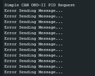
Troubleshooting: Why Might You See Incorrect Data?
The user in the original example encountered an issue with incorrect data display, indicated by the screenshot. Here are common reasons why you might not get the expected engine speed readings:
-
Wiring Issues: Incorrect wiring between the MCP2515, Arduino, and OBD2 port is the most frequent cause. Double-check your connections, especially CAN_H and CAN_L lines, and the power and ground connections. Ensure proper termination resistors are used on the CAN bus if required by your MCP2515 module.
-
CAN Bus Speed Mismatch: OBD2 typically uses 500kbps. Ensure the
CAN0.begin(MCP_STDEXT, CAN_500KBPS, MCP_8MHZ)line in your code correctly sets the baud rate toCAN_500KBPS. Mismatched baud rates will lead to communication errors. -
Incorrect CAN IDs: While the provided CAN IDs (
FUNCTIONAL_ID,LISTEN_ID,REPLY_ID) are commonly used for OBD2, they can vary slightly depending on the vehicle and ECU. If you are not getting responses, you might need to research the specific CAN IDs for your vehicle or use CAN bus sniffing tools to identify the correct IDs. -
PID Not Supported: While PID
0C(Engine Speed) is a widely supported standard PID, it’s possible that a very old or non-standard vehicle might not support it. You can first request PID00(Supported PIDs [01-20]) to check which PIDs are supported by your vehicle’s ECU. -
Data Interpretation Errors: Incorrectly parsing the response data or applying the wrong formula to calculate RPM will lead to wrong readings. Carefully check the OBD2 standard documentation for PID
0Cto understand the correct data format and calculation method for your vehicle’s protocol. -
MCP2515 Initialization Issues: If the “Error Initializing MCP2515…” message appears in the serial monitor, there’s a problem with the MCP2515 module setup. Check the CS pin configuration, SPI wiring, and ensure the MCP2515 module is correctly powered.
Next Steps: Improving Your OBD2 Arduino Project
This guide provides a basic framework for requesting engine speed data. To build a more robust OBD2 Arduino project, consider these improvements:
- Data Parsing and RPM Calculation in Code: Implement code to automatically parse the response, extract the relevant data bytes, and calculate the RPM value directly in your Arduino sketch. Display the RPM value clearly on the serial monitor.
- Error Handling: Add error handling to your code to gracefully manage situations like no response from the ECU or invalid data.
- Requesting Multiple PIDs: Extend your code to request and display other useful OBD2 PIDs, such as coolant temperature, intake air temperature, throttle position, etc.
- Data Visualization: Instead of just serial monitor output, consider using an LCD screen or sending data to a computer or smartphone app for graphical visualization of the car’s data in real-time.
- Custom Dashboards and Alerts: Build custom dashboards to display the data you are interested in and set up alerts for abnormal readings (e.g., high coolant temperature).
By combining the MCP2515, Arduino, and your programming skills, you can unlock a wealth of information from your car’s OBD2 system and create exciting and practical automotive projects. Remember to always consult your vehicle’s service manual and OBD2 documentation for specific details related to your car model.
 image
image